Motor driving apparatus

Inactive Publication Date: 2005-11-24
COLLABO INNOVATIONS INC
View PDF2 Cites 45 Cited by
  • Summary
  • Abstract
  • Description
  • Claims
  • Application Information

AI Technical Summary

Benefits of technology

[0016] a switching controlling means for outputting a drive signal (PWM signal) for performing high-frequency switching control according to a command signal to the above-mentione

Problems solved by technology

In such a method, when the rotor rotating speed is slow, for example, at starting, the position detection signals include many detection errors since back electromotive forces is small, etc.
That is, since displacement in the detected phase arises with respect to the real phase which should be detect

Method used


Image

  • Motor driving apparatus
  • Motor driving apparatus
  • Motor driving apparatus

Examples


embodiment 1

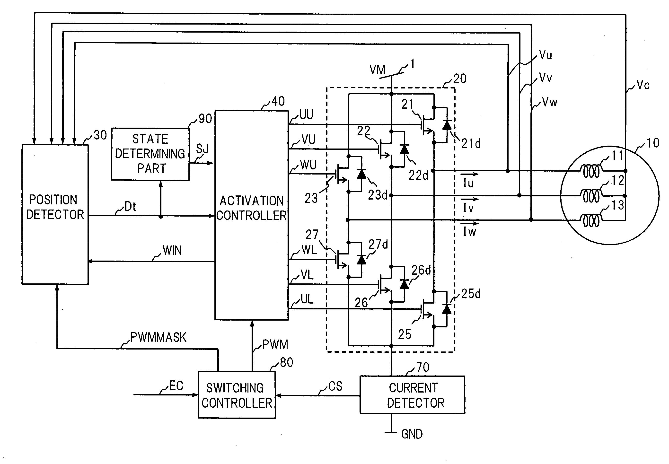
[0067]FIG. 1 is a block diagram showing a configuration of a motor driving apparatus in accordance with Embodiment 1 of the present invention. A motor 10 to be controlled by the motor driving apparatus in accordance with Embodiment 1 comprises a rotor (not shown) having a field part formed of a permanent magnet and a stator (not shown) in which three-phase windings 11, 12 and 13 are Y-connected.

[0068] As shown in FIG. 1, the motor driving apparatus has an outputting part 20, a position detector 30 as a position detecting means, an activation controller 40 as an activation controlling means, a current detector 70, a switching controller 80 as a switching controlling means and a state determining part 90 as a state determining means.

[0069] The outputting part 20 is disposed between a power supply 1 and the ground (GND) and bridge configuration is achieved by three high-side power transistors 21, 22, and 23 and three low-side power transistors 25, 26, and 27. The three-phase windings...

embodiment 2

[0097] Next, a motor driving apparatus in accordance with Embodiment 2 of the present invention will be described below. FIG. 8 is a block diagram showing a configuration of the motor driving apparatus in accordance with Embodiment 2 of the present invention. The motor driving apparatus in accordance with Embodiment 2 is different from the motor driving apparatus in accordance with Embodiment 1 in that a predetermined cycle OFF circuit 100 is provided. As shown in FIG. 8, the predetermined cycle OFF circuit 100 is configured so as to receive inputs of the PWM signal from the switching controller 80 and the state determination signal SJ from the state determining part 90, output a PWMA signal to the activation controller 40 and outputs a PWMMASK signal to the position detector 30. Since the other configuration and operation are the same as those in accordance with Embodiment 1, description thereof is omitted in Embodiment 2.

[0098]FIG. 9 is a block diagram showing a specific configur...

embodiment 3

[0108]FIG. 12 is a block diagram showing a configuration of a motor driving apparatus in accordance with Embodiment 3 of the present invention. The motor driving apparatus in accordance with Embodiment 3 is different from the above-mentioned Embodiment 1 in the configuration of a position detector 30A and a switching controller 80A. Other configuration and operation are the same as those described in accordance with Embodiment 1.

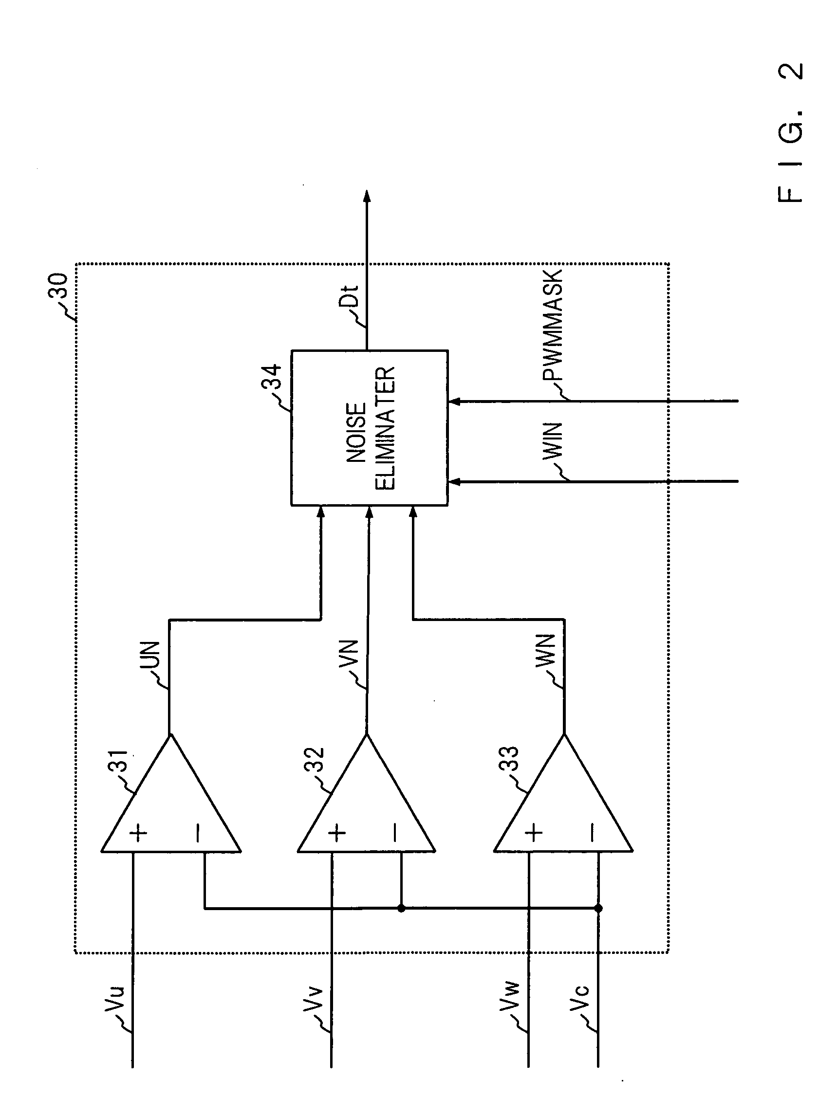
[0109]FIG. 13 is a block diagram showing a specific configuration of the position detector 30A in accordance with Embodiment 3. In the position detector 30A, a reversal processing circuit 35 is added to the position detector 30 of Embodiment 1. The position detector 30A compares the three-phase terminal voltages Vu, Vv and Vw with the center tap voltage Vc of the motor 10 and detects zero-crossing of the back electromotive forces which appear in a non-activation phase (open phase) of the windings according to reversal processing output of the comparison res...


PUM


Abstract

A Motor driving apparatus adjusts activation start timing of high-side activation control signals UU, VU, WU and the low-side activation control signals UL, VL, and WL with a state determination signal SJ in an activation controller 40, in the period from starting to the time when rotor rotating speed reaches a predetermined value, sets the activation start timing earlier than in normal times to perform leading phase activation control, and in normal times when the rotor rotating speed is a predetermined value or more, controls activation start timing in efficient and optimum phase. Hence, the motor driving apparatus can carry out stable PWM sensorless starting without any starting failure such as oscillation, loss of synchronism and reverse rotation and shorten starting time.

Description

BACKGROUND OF THE INVENTION [0001] This invention relates to a motor driving apparatus which detects zero-crossing of back electromotive forces generated in a non-activation phase (open phase) in windings to perform position sensorless PWM driving of the motor, in particular, a starting control method in the motor driving apparatus. [0002] In recent years, a brushless motor has been generally employed to drive a recording medium such as a hard disk and an optical disk, or a fan, a compressor and the like in air conditioning equipment. For a wide range of variable speed control or reduction in electricity consumption, such brushless motor is driven by PWM operation by using an inverter device. In the brushless motor having three-phase windings, to detect position of a magnetic pole of the rotor, position sensors such as Hall devices are generally arranged every 120 degrees of electrical angle. In opposition to the brushless motor having such position sensors, for the purpose of reduc...

Claims


Application Information

Patent Timeline
IPC IPC(8): H02P6/06H02P6/18H02P6/08H02P6/15H02P6/182H02P6/21H02P6/28H02P7/06
CPCH02P2209/07H02P6/20
Inventor MORI, HIDEAKIKUROSHIMA, SHINICHI
Owner COLLABO INNOVATIONS INC
Why Eureka
Try Eureka