Objective optical system and optical pickup device using it

a technology of optical pickup and optical recording medium, which is applied in the direction of optical recording heads, instruments, data recording, etc., can solve the problems of reducing the diffraction efficiency and the stability of tracking, and achieves improved diffraction efficiency of light beams, efficient focus, and increased freedom in selecting positions

Inactive Publication Date: 2005-11-24
FUJI PHOTO OPTICAL CO LTD
View PDF9 Cites 16 Cited by
  • Summary
  • Abstract
  • Description
  • Claims
  • Application Information

AI Technical Summary

Benefits of technology

[0011] The present invention relates to an objective optical system for optical recording media that can efficiently focus each of three light beams on a corresponding one of three optical recording media with different technical standards of the substrate thickness, the wavelengths of the three light beams, and the numerical aperture (NA) of the objective optical system for each of the three light beams. Using three collimated light beams of three different wavelengths in the objective optical system of the present invention allows for increased freedom in selecting the position of the objective optical system and improved diffraction efficiency of the light beams, and concurrently increases the stability of the tracking. The present invention further relates to such an objective optical system with the diffractive optical element being also a lens element of the objective optical system. The present invention further relates to an optical pickup device using this objective optical system.

Problems solved by technology

Additionally, if diverging or converging light is incident on the diffractive optical element, there are problems of the diffraction efficiency being reduced due to the angle of incidence of the light rays on the diffractive grooves of the diffractive optical element being tilted from the desired angle of incidence, and there are problems of the stability of the tracking being decreased.

Method used


Image

  • Objective optical system and optical pickup device using it
  • Objective optical system and optical pickup device using it
  • Objective optical system and optical pickup device using it

Examples


Embodiment Construction

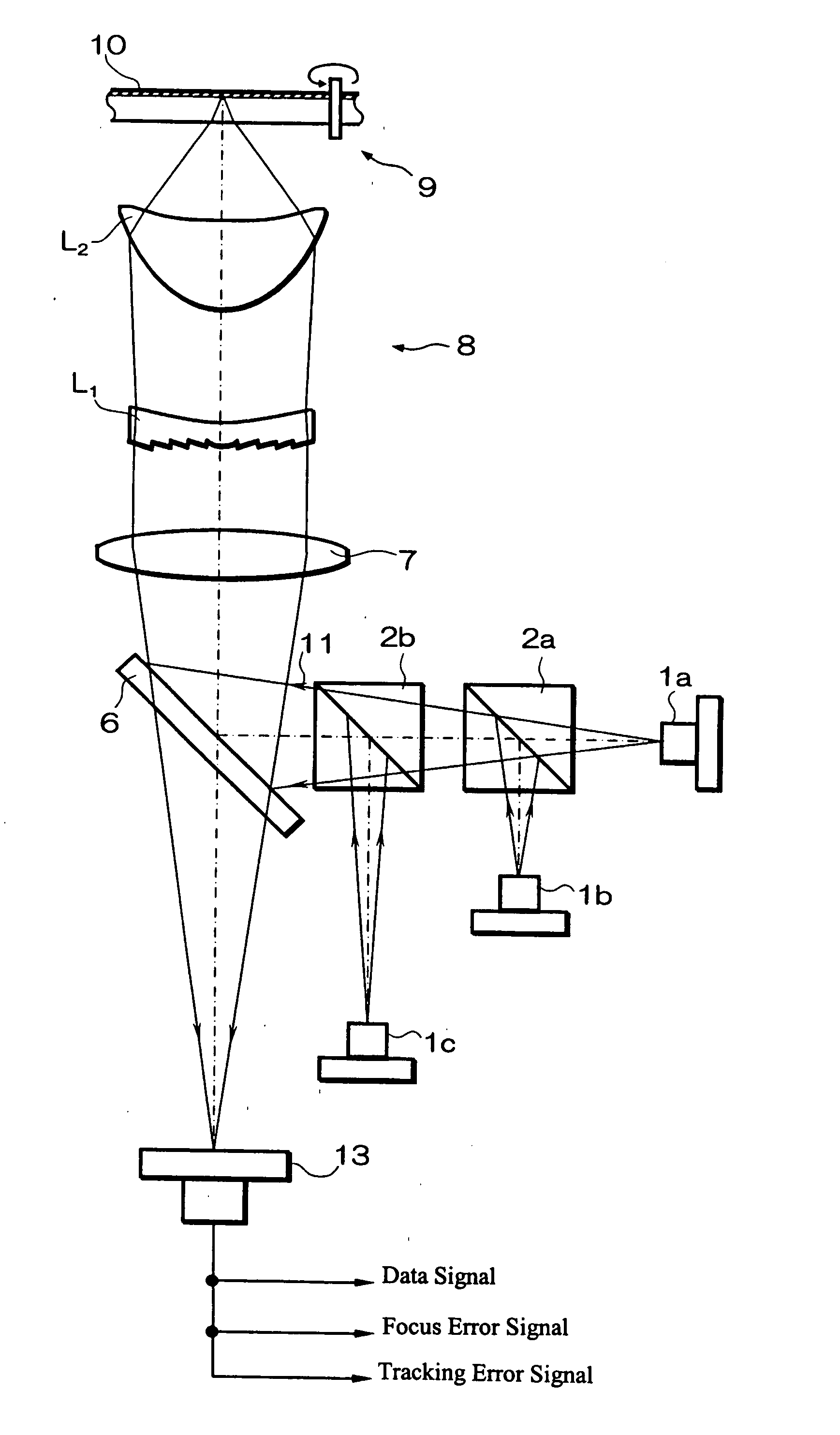
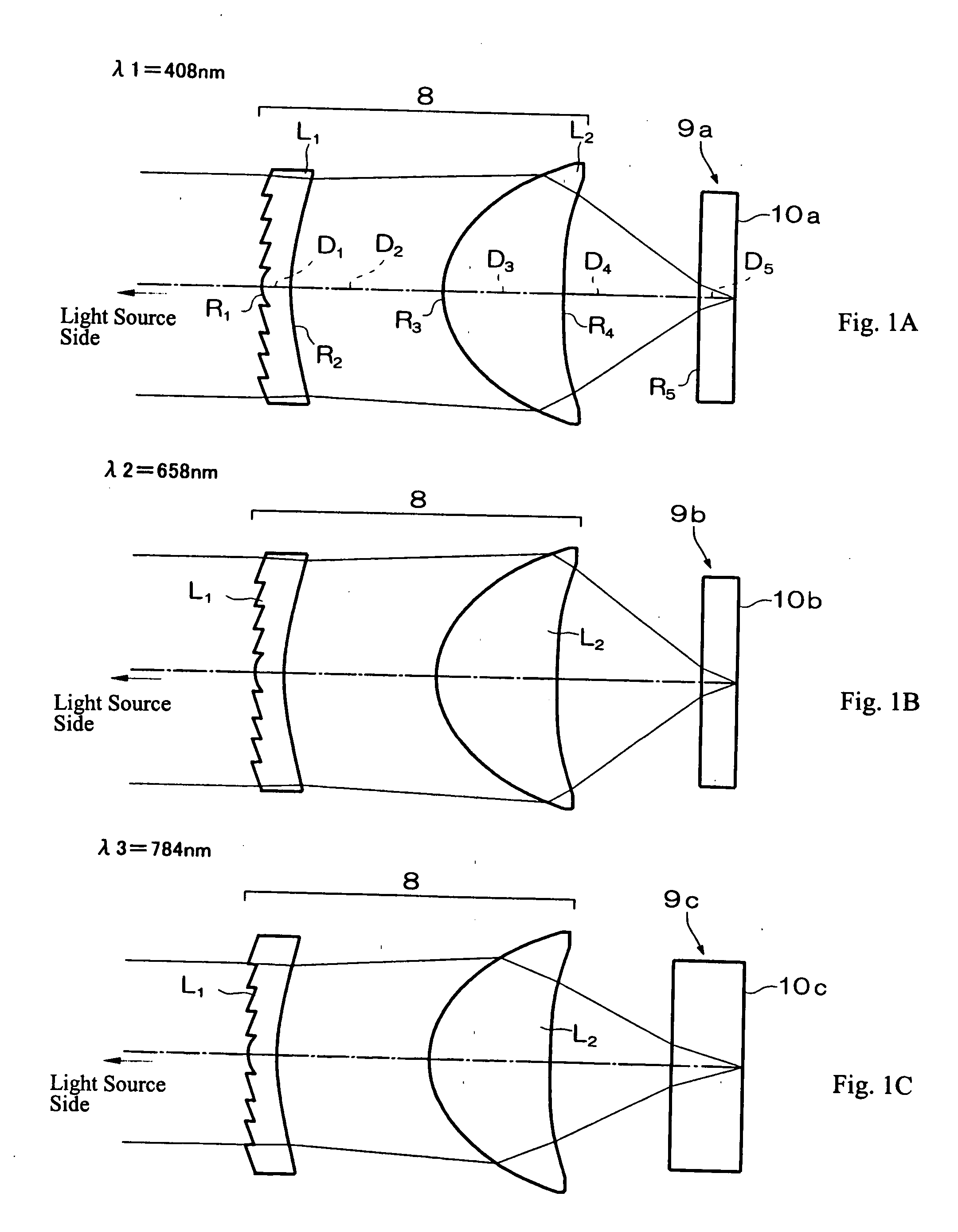
[0016] The present invention relates to an objective optical system for optical recording media that can be used to focus each of three different light beams of three different wavelengths, λ1, λ2, and λ3, from a light source to a different desired position for each of the first, second and third optical recording media of substrate thicknesses, T1, T2, and T3, respectively, for recording and reproducing information.

[0017] The objective optical system includes, from the light source side: a diffractive optical element with one surface of the diffractive optical element being a diffractive surface defined by a phase function Φ, as will be discussed in detail later; and an objective lens of positive refractive power with both surfaces being rotationally symmetric aspheric surfaces. The phase function Φ is chosen so that the objective optical system is able to focus each of the three different light beams of three different wavelengths, λ1, λ2, and λ3, at a different desired position ...


PUM

PropertyMeasurementUnit
wavelengthaaaaaaaaaa
thicknessaaaaaaaaaa

Abstract

An objective optical system is formed of a diffractive optical element with a diffractive surface formed on a planar ‘virtual surface’ (i.e., a surface that would be planar but for the diffractive structure) and an objective lens for focusing three collimated light beams of three different wavelengths at three different numerical apertures onto desired positions of three different recording media with substrates of different thicknesses, such as an AOD, a DVD, and a CD, that introduce different amounts of spherical aberration in the focused beams. The objective optical system provides compensating spherical aberration to the three light beams while keeping equal the distance between the diffractive optical element and the objective lens, and focuses second-order diffracted light of one wavelength and first-order diffracted light of the other two wavelengths. An optical pickup device includes the objective optical system, the recording media, and a light source supplying the three light beams.

Description

TECHNICAL FIELD OF THE INVENTION [0001] The present invention relates to an objective optical system for an optical recording medium that, when recording or reproducing information, efficiently focuses light of any one of three different wavelengths onto an appropriate corresponding recording medium according to standardized characteristics such as the numerical aperture of the objective optical system used, the wavelength of the light selected, and the substrate thickness of the optical recording medium. The present invention also relates to an objective optical system for an optical recording medium where a diffractive optical element is used to diffract light in order to efficiently focus light of any one of the three wavelengths onto a corresponding one of the three optical recording media, and it also relates to an optical pickup device using such an objective optical system. BACKGROUND OF THE INVENTION [0002] In recent years, a variety of optical recording media have been deve...

Claims


Application Information

Patent Timeline
Patent Type & Authority Applications(United States)
IPC IPC(8): G11B7/135G11B7/00
CPCG11B7/1367G11B7/1374G11B2007/13727G11B7/13922G11B2007/0006G11B7/1376
Inventor KATSUMA, TOSHIAKIMORI, MASAOORI, TETSUYAKITAHARA, YU
Owner FUJI PHOTO OPTICAL CO LTD
Why Eureka
Try Eureka