Fault recovery method and program therefor

a fault recovery and program technology, applied in the field of fault recovery methods and programs therefor, can solve problems such as errors in lsp fault recovery, system poor speed enhancement, and links other than links often becoming faulty at the same time, and achieve the effect of stable fault recovery processing

Inactive Publication Date: 2005-11-24
NEC CORP +1
View PDF1 Cites 23 Cited by
  • Summary
  • Abstract
  • Description
  • Claims
  • Application Information

AI Technical Summary

Benefits of technology

[0013] It is an object of the present invention to provide a fault recovery method and a program therefor which allow stable fault recovery processing while eliminating the possibility to select another link in a fault zone as an alternative path.
[0017] According to the present invention, since the node performing fault recovery receives state information notifications of links other than a link that was being used as the LSP, in addition to the fault event notification which indicates fault occurrence, before performing alternative path calculation based on them, it is possible to enhance recovery rate when fault recovery is performed based on what is called dynamic restoration system.

Problems solved by technology

This system is poor in speed enhancement as compared with the protection system.
When a network configuration, for example a WDM (Wavelength Division Multiplexing) network configuration, such that a plurality of links are accommodated in one transmission line such as a fiber, is taken into account, if there occurs a fault in a link that was being used as the LSP, links other than the link often become faulty at the same time.
Thus, when the node which performs fault recovery calculates (again) a path for restoration, if the restoration processing is carried out before topology states are synchronized sufficiently, this may result in causing an error in LSP fault recovery.

Method used


Image

  • Fault recovery method and program therefor
  • Fault recovery method and program therefor

Examples


Embodiment Construction

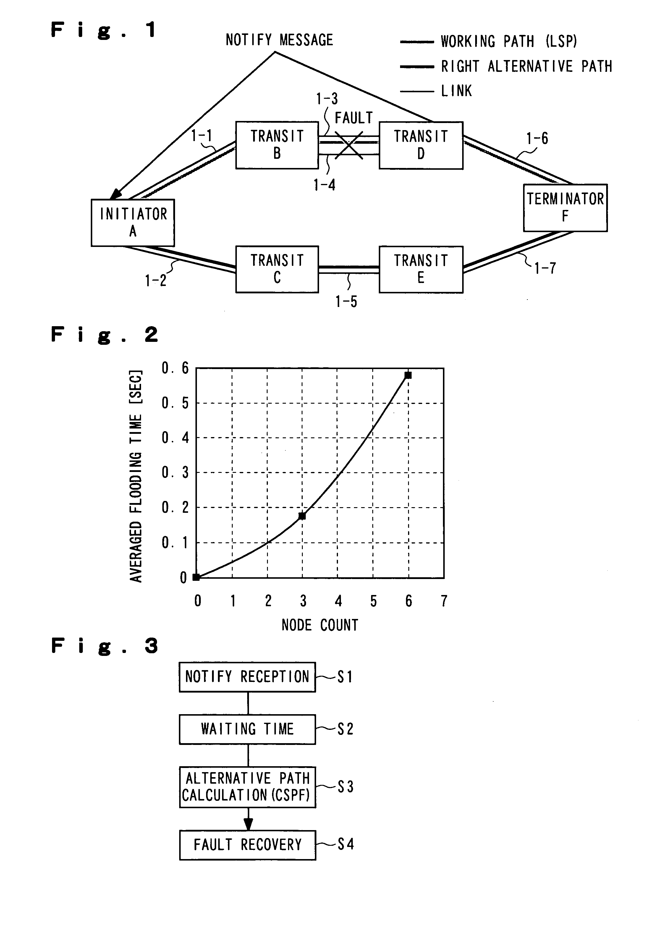
[0022] With reference to the drawings, embodiment of the present invention is described in detail below. FIG. 1 illustrates a configuration of a network to which the present invention is applied. This network is configured by connecting nodes A through F by lines of optical fibers or the like, in which network links 1-1, 1-2, 1-5, 1-6 and 1-7 are arranged between nodes A-B, nodes A-C, nodes C-E, nodes D-F and nodes E-F, respectively. Two network links 1-3 and 1-4 are arranged between nodes B-D. Here, it is assumed that node A is an initiator node (Initiator), node F is a terminator node (Terminator), and a working path (LSP) is established at a route through node A—transit node (Transit) B—transit node (Transit) D—node F.

[0023] If there occur faults on the link 1-3 between the transit nodes B and D and also on the link 1-4, simultaneously, the node in the fault zone (which is here, “transit node D”) performs fault localization and notifies the node which performs fault recovery (wh...


PUM


Abstract

When there occurs a fault in any path of the MPLS or GMPLS network, a node which has detected the fault sends a notify message which is fault event information. A node which performs fault recovery receives the notify message (S1) and counting of the waiting time is triggered by this reception (S2). During this waiting time, LSA of OSPF is collected. When the waiting time is terminated, the node which performs fault recovery calculates alternative path based on the notify message and the LSA of OSPF (S3) and carries out fault recovery by restoration (S4).

Description

BACKGROUND OF THE INVENTION [0001] 1. Field of the Invention [0002] The present invention relates to a fault recovery method and a program therefor. Particularly, the present invention relates to a fault recovery method which allows stable fault recovery processing in restoration which is a highly-reliable fault recovery method of an LSP (Label Switched Path) in a MPLS (Multi Protocol Label Switching) or GMPLS (Generalized MPLS) network, and a program therefor. [0003] 2. Description of the Related Art [0004] Known as a conventional network fault recovery system are a protection system and a restoration system. According to the protection system, a protection path is prepared in advance for a working path and when there occurs a fault in the working path, the protection path is used as LSP. In this system, since a protection path is reserved in advance as an alternative path and there is no need to set a new fault-free path by calculating again, rapid recovery from fault becomes poss...

Claims


Application Information

Patent Timeline
Patent Type & Authority Applications(United States)
IPC IPC(8): H04L1/00H04L1/22H04L45/24
CPCH04L1/22H04L45/00H04L45/02H04L45/50H04L45/22H04L45/28H04L45/023H04L45/03
Inventor HAYASHI, MICHIAKIOGAKI, KENICHITANAKA, HIDEAKIHARADA, RYOUICHIFUNASAKI, TOMOSHIGETANUMA, HIROYUKI
Owner NEC CORP
Why Eureka
Try Eureka