Image processing apparatus and method, and recording medium and program used therewith

a technology of image processing and recording media, applied in the field of image processing apparatuses and methods, and recording media and programs, can solve the problems of inability to perform recursive gradient operations, and inability to achieve real-time processing. the effect of improving the accuracy of motion vector detection

Inactive Publication Date: 2005-11-24
SONY CORP
View PDF5 Cites 36 Cited by
  • Summary
  • Abstract
  • Description
  • Claims
  • Application Information

AI Technical Summary

Benefits of technology

[0007] The present invention has been made in view of the above circumstances, and it is an object of the present invention to enable selection of an initial vector which increases the accuracy of motion vector detection in the gradient method.
[0017] According to the present invention, an initial vector that improves the accuracy of motion vector detection by the gradient method can be selected. In particular, in the vicinity of a boundary in which movement is detected, the accuracy of motion vector detection can be improved.

Problems solved by technology

Although the gradient method can produce a highly accurate result of detection for a minute movement, it is not practical because, when a movement in an actual moving image is detected, such a movement is too large.
However, simply recursively performing the gradient operation takes a long time in the case of performing real-time processing.
Accordingly, a problem occurs in that a false initial vector (initial vector having different movement) is selected.
In addition, this results in a decrease in the accuracy of motion vector detection in the subsequent stage by the gradient method, thus causing image deterioration.

Method used


Image

  • Image processing apparatus and method, and recording medium and program used therewith
  • Image processing apparatus and method, and recording medium and program used therewith
  • Image processing apparatus and method, and recording medium and program used therewith

Examples


Embodiment Construction

[0077] Embodiments of the present invention are described below with reference to the accompanying drawings.

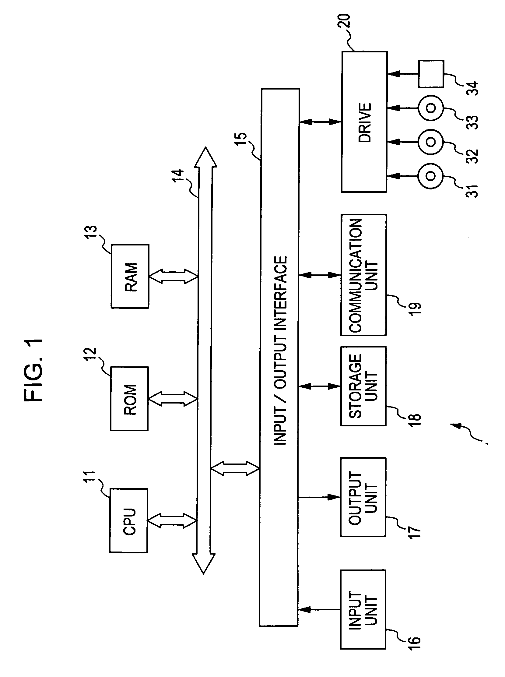
[0078]FIG. 1 shows an example of the configuration of a signal processing apparatus 1 to which the present invention is applied. The signal processing apparatus 1 is formed by, for example, a personal computer or the like. In FIG. 1, a central processing unit (CPU) 11 executes various types of processing in accordance with programs stored in a read-only memory (ROM) 12 or a storage unit 18. A random access memory (RAM) 13 stores a program to be executed by the CPU 11 and data, if needed. The CPU 11, the ROM 12, and the RAM 13 are connected to one another by a bus 14.

[0079] The CPU 11 connects to an input / output interface 15 through the bus 14. The input / output interface 15 connects to an input unit 16 including a keyboard, a mouse, and a microphone, and to an output unit 17 including a display and a speaker. The CPU 11 executes various types of processing in response to inst...


PUM


Abstract

A past frame at a past time has a motion vector in a block, and a reference frame at a reference time has a different block which is a motion-compensated block identical in position to a terminal point of a motion vector in the block. When a gradient method is used to detect a motion vector in the different block in the reference frame, a motion vector which is identical in magnitude and orientation to a motion vector and whose initial point is the different block in the reference frame is used as a candidate vector for initial vectors. The present invention is applicable to a signal processing apparatus for performing frame frequency conversion from a 24P signal to a 60P signal.

Description

BACKGROUND OF THE INVENTION [0001] 1. Field of the Invention [0002] The present invention relates to image processing apparatuses and methods, and recording media and programs used therewith. In particular, the present invention relates to an image processing apparatus and method that have increased accuracy of motion vector detection, and to a recording medium and program used therewith. [0003] 2. Description of the Related Art [0004] In an image processing apparatus for converting the frame frequency of an image, the gradient method is used as a method for detecting a motion vector of a block of interest. Although the gradient method can produce a highly accurate result of detection for a minute movement, it is not practical because, when a movement in an actual moving image is detected, such a movement is too large. Accordingly, as disclosed in Japanese Unexamined Patent Application Publication No. 60-158786, detection is achieved by recursively performing gradient operation. [00...

Claims


Application Information

Patent Timeline
Patent Type & Authority Applications(United States)
IPC IPC(8): G06T3/40G06T7/20H04N5/14H04N7/01H04N7/12
CPCG06T3/4007G06T7/2026H04N7/014G06T2207/20021H04N5/145G06T2207/10016G06T7/238G06T1/20G06T7/00G06T7/20H04N7/01
Inventor NAKAMURA, YUKIHIROTAKAHASHI, YASUAKIHORISHI, TAKASHIKAWAGUCHI, KUNIOYOSHIWARA, NORIFUMIKAINO, AKIHIKOCHOKI, YUTA
Owner SONY CORP
Why Eureka
Try Eureka