Oil-sealed vane rotary vacuum pump

a vacuum pump and oil seal technology, applied in the direction of piston pumps, magnetic circuit rotating parts, magnetic circuit shapes/forms/construction, etc., can solve the problems of positive influence on vibration and noise, reduce manufacturing costs, and reduce failure danger, so as to reduce power consumption, uniform torque, and uniform relationship

Inactive Publication Date: 2005-11-24
PFEIFFER VACUUM GMBH
View PDF20 Cites 14 Cited by
  • Summary
  • Abstract
  • Description
  • Claims
  • Application Information

AI Technical Summary

Benefits of technology

[0013] According to the invention, the oil-sealed vane rotary vacuum pump is equipped with brushless direct current motor that consists of permanent magnets arranged on the shaft of the pumping system, and stationary coils which are controlled by the control electronics. These motors have a very uniform relationship between the torque and rotational speed and rotational angle. Thus, already at a very low rotational speed, the motor starting torque is brought up to almost a full torque. Thereby, a motor can be used that has, in comparison with an asynchronous alternating current motor, a uniform torque and a noticeably reduced power consumption. In addition, the motor has reduced dimensions and, therefore, the pump itself can be formed more compact. Further, the uniform torque provides for a noticeably quieter running, which positively influences the vibration and noise. Further, instead of several shafts used in conventional pumps, only one shaft is used, which reduces the manufacturing costs and the danger of failure.

Problems solved by technology

Further, the uniform torque provides for a noticeably quieter running, which positively influences the vibration and noise.
Further, instead of several shafts used in conventional pumps, only one shaft is used, which reduces the manufacturing costs and the danger of failure.

Method used


Image

  • Oil-sealed vane rotary vacuum pump
  • Oil-sealed vane rotary vacuum pump
  • Oil-sealed vane rotary vacuum pump

Examples


Embodiment Construction

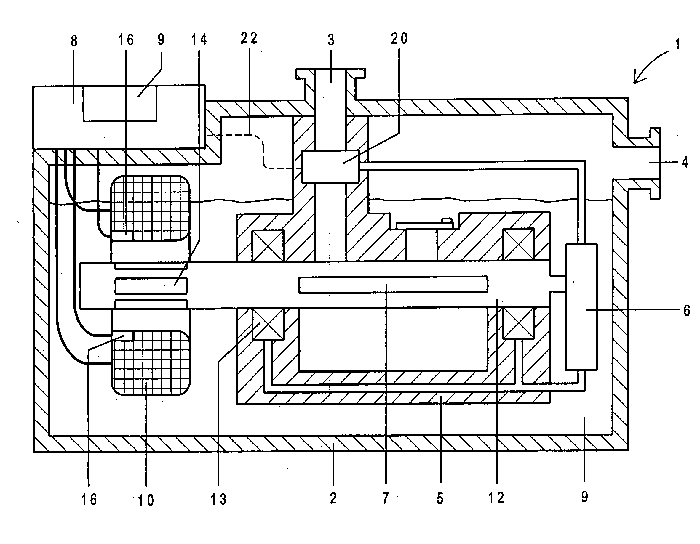
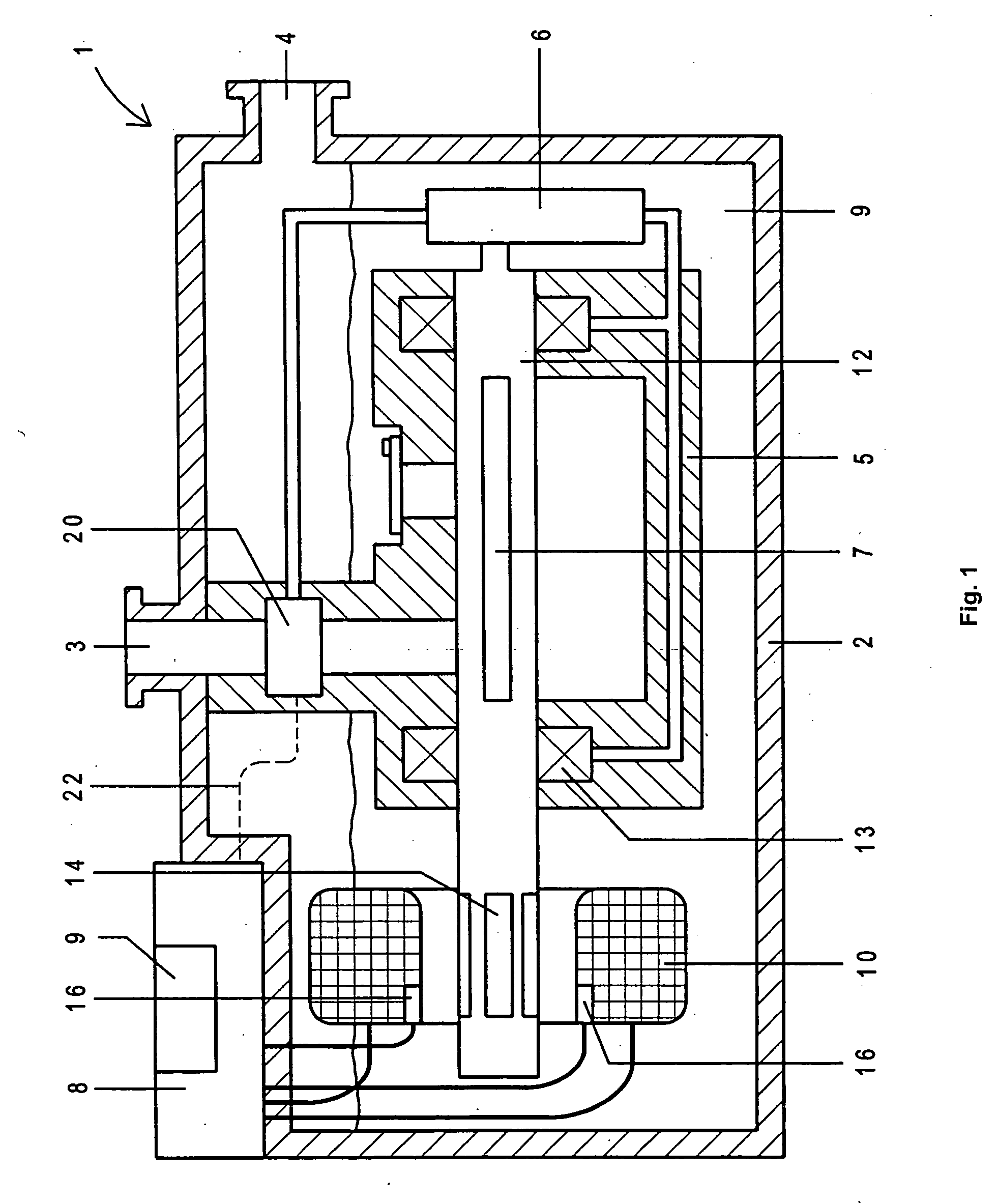
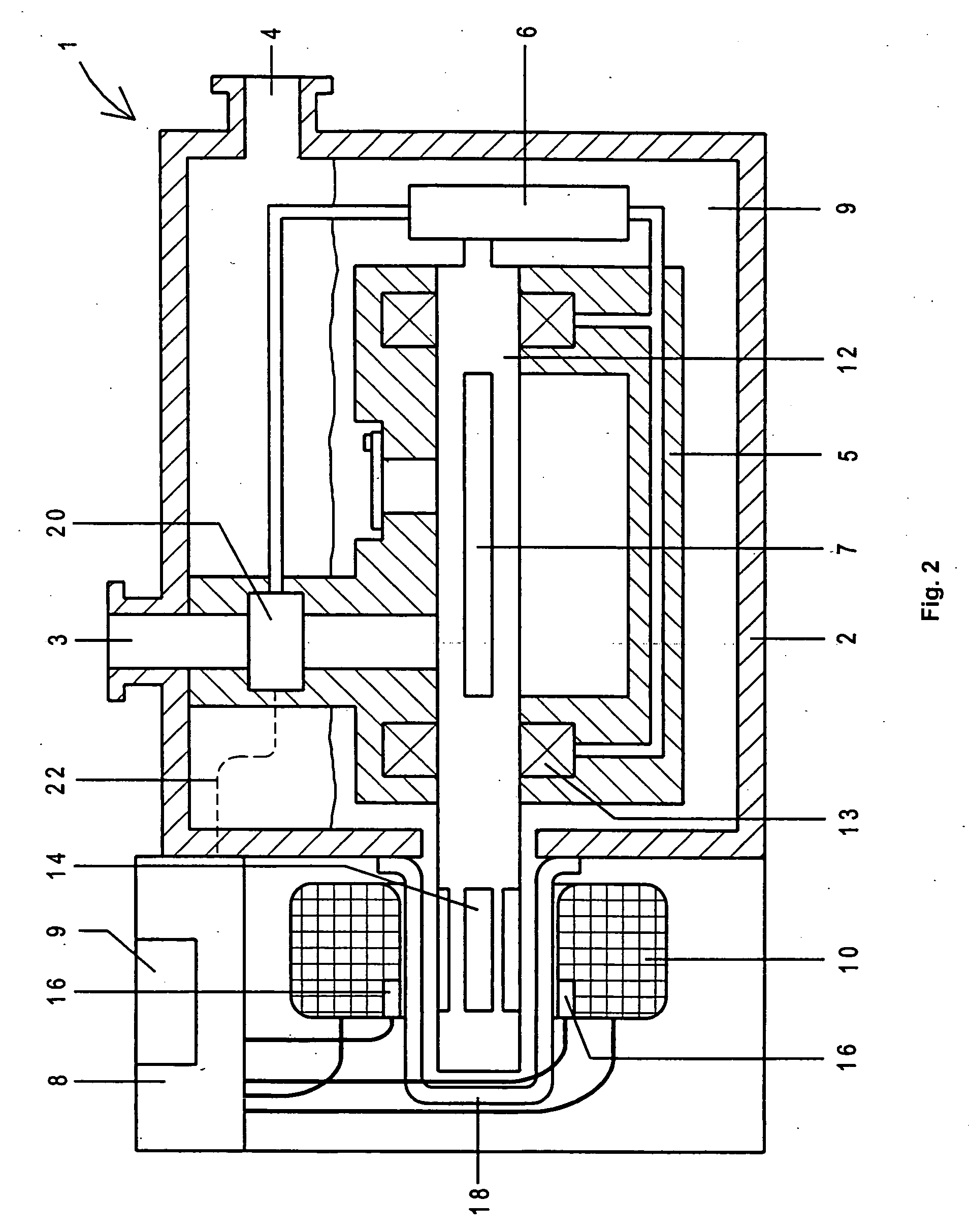
[0019] An oil-sealed, vane rotary vacuum pump 1 according to the present invention, which is shown in FIG. 1, includes a housing 2 having a gas inlet 3 and a gas outlet 4, and a pumping system 5 located in the interior of the housing 2. The pumping system 5 includes a shaft 12 which is supported in bearings 13. The pumping effect is produced by rotation of the shaft 12 together with rotary vanes 7. A hydraulic oil pump 6 provides for lubrication of the bearings 13 which are formed as bearings and supplies a high vacuum safety valve 20 with oil. This safety valve 20 is closed when the shaft 12 does not rotate any more, which leads to reduction in oil pressure provided by the oil pump 6.

[0020] On the shaft 12, there are arranged a plurality of permanent magnets 14 which are surrounded by coils 10. The coils 10 produce a rotatable magnetic field the position of which changes by an electronic commutation and thereby provides for rotation of the shaft 12. Instead of two shafts of conven...


PUM


Abstract

An oil-sealed vane rotary vacuum pump includes at least one pump stage arranged in the housing and having a cylindrical chamber, a shaft excentrically arranged in the cylindrical chamber and provided with vanes, and a drive for driving the shaft and having a plurality of permanent magnets arranged on the shaft and stationary electrical coils surrounding the permanent magnets and producing a rotatable magnetic field, and control electronics for controlling the coils and arranged in a removable housing part of the pump.

Description

BACKGROUND OF THE INVENTION [0001] 1. Field of the Invention [0002] The present invention relates to an oil-sealed vane rotary vacuum pump including a housing, at least one pump stage arranged in the housing and having a cylindrical chamber, a shaft excentrically arranged in the cylindrical chamber and provided with vanes, and drive means for driving the shaft. [0003] 2. Description of the Prior Art [0004] Vane rotary vacuum pumps play an important role in generation of vacuum. They are used to generate low and high vacuum with an end pressure up to about 6*10−3 mbar and are used in industry, research, and laboratories. Traditionally, these pumps are used as for vacuum pumps for pumps such as Roots vacuum pumps and turbomolecular pumps which are not sealed against the atmospheric pressure. Dependent on their use, they are formed as one stage or multi-stage pumps. [0005] The vane rotary vacuum pumps of the type described above belong to a class of oil-filled positive displacement pum...

Claims


Application Information

Patent Timeline
Patent Type & Authority Applications(United States)
IPC IPC(8): F04C18/344F04C29/00H02K1/27
CPCF04C18/3442F04C2270/701F04C29/0085F04C25/02
Inventor CONRAD, ARMINLOSCH, WOLFANG
Owner PFEIFFER VACUUM GMBH
Why Eureka
Try Eureka