
Polymer treating method and apparatus

a polymer and treatment method technology, applied in the direction of chemistry apparatus and processes, manufacturing tools, chemical/physical/physical-chemical processes, etc., can solve the problems of inability to disclose an effective method for separating thermoplastic materials, difficult to apply to material recycling, and high cost of wastage disposal, etc., to achieve the effect of reducing the pressure fluctuation, facilitating the reaction with reaction agents, and sufficient reaction tim

Active Publication Date: 2005-11-24
HITACHI METALS LTD
View PDF1 Cites 9 Cited by
  • Summary
  • Abstract
  • Description
  • Claims
  • Application Information

AI Technical Summary

Benefits of technology

[0013] It is an object of the invention to provide a polymer treating method that a polymer treatment product discharged from the reaction vessel can be stably supplied to the degassing extruder while preventing pressure fluctuation caused by the abrupt expansion of reaction agent.
[0014] It is a further object of the invention to provide a polymer treating apparatus that a polymer treatment product discharged from the reaction vessel can be stably supplied to the degassing extruder while preventing pressure fluctuation caused by the abrupt expansion of reaction agent.
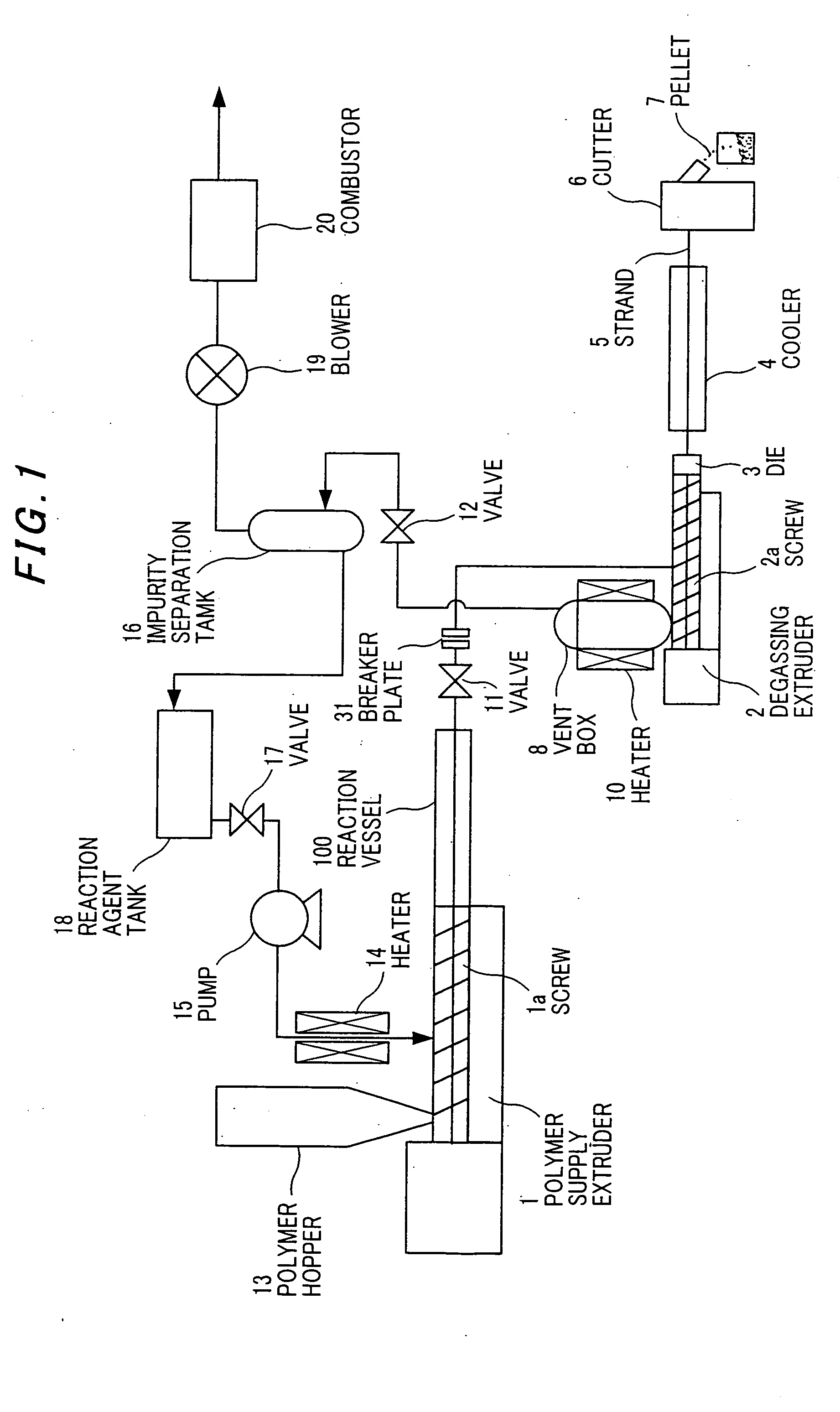
[0054] Thus, in the invention, the degassing extruder is provided with the vent box as vent back that has a volume of equal to or more than the reactor vessel. Thereby, the reaction agent can be stably separated from the polymer treatment product. Therefore, the polymer treatment product discharged from the reaction vessel can be stably supplied to the degassing extruder while preventing pressure fluctuation caused by the abrupt expansion of reaction agent.
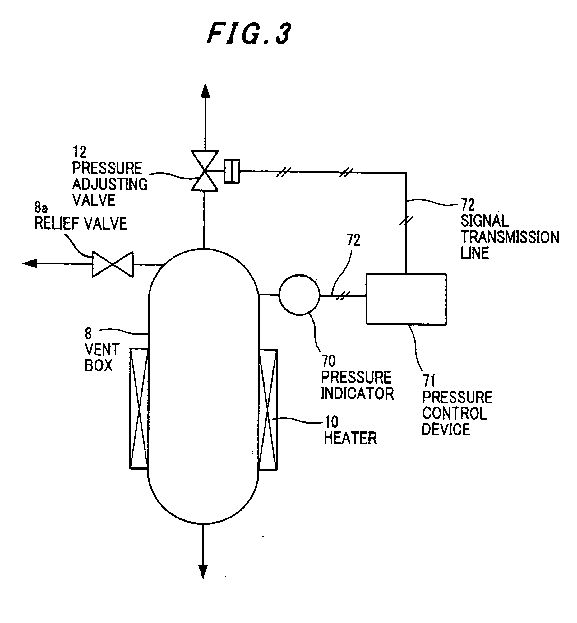
[0055] Even when resin containing a great amount of reaction agent is discharged from the polymer material supplying extruder to the degassing extruder, due to the large volume of vent box, the inner pressure of degassing extruder can be sufficiently decompressed while preventing the blockage in exhaust port of the vent box. Thus, the vent box serves as a buffer to pressure fluctuation. Thereby, pressure fluctuation in subsequent portions can be also suppressed, and the polymer treatment product can be subjected to the continuous and uniform molding.
[0056] It is more desirable that, in order to prevent the scattering of reaction agent caused by excess pressure rise, the volume of vent box is about Pv-times greater than that of the reactor vessel where the inner pressure of reactor vessel is Pv [MPa] . Thereby, even if gas in the reactor vessel is all flown into the vent box, the pressure of vent box can be kept lower than 1 MPa.
[0059] The method and apparatus of the invention are especially effective for the case of using a cross-linked polymer as the polymer and alcohols or a mixture containing alcohols as the reaction agent. Also, they are very effective for a case that at a high pressure as supercritical state, the suppression of pressure fluctuation as well as securing a sufficient reaction time is desired to facilitate the reaction with reaction agent.

Problems solved by technology

In recent years, as environment problems become important, the cost in disposal of wastage tends to increase.
However, a thermosetting resin, a cross-linked polymer, rubber etc. are difficult to apply to the material recycling since the fluidization property thereof cannot be obtained even by heating due to the molecular three-dimensional network.
However, prior art 1 does not disclose an effective means for separating the thermoplastic material after mixing the reaction agent with the thermosetting resin.
However, since the extruder of prior art 2 has to be disposed spatially, the manufacturing cost of apparatus increases.
Further, if the polymer generated sticks to the wall of separation bath, it is difficult to supply the polymer into the degassing extruder.

Method used


Image

  • Polymer treating method and apparatus
  • Polymer treating method and apparatus
  • Polymer treating method and apparatus

Examples


Embodiment Construction

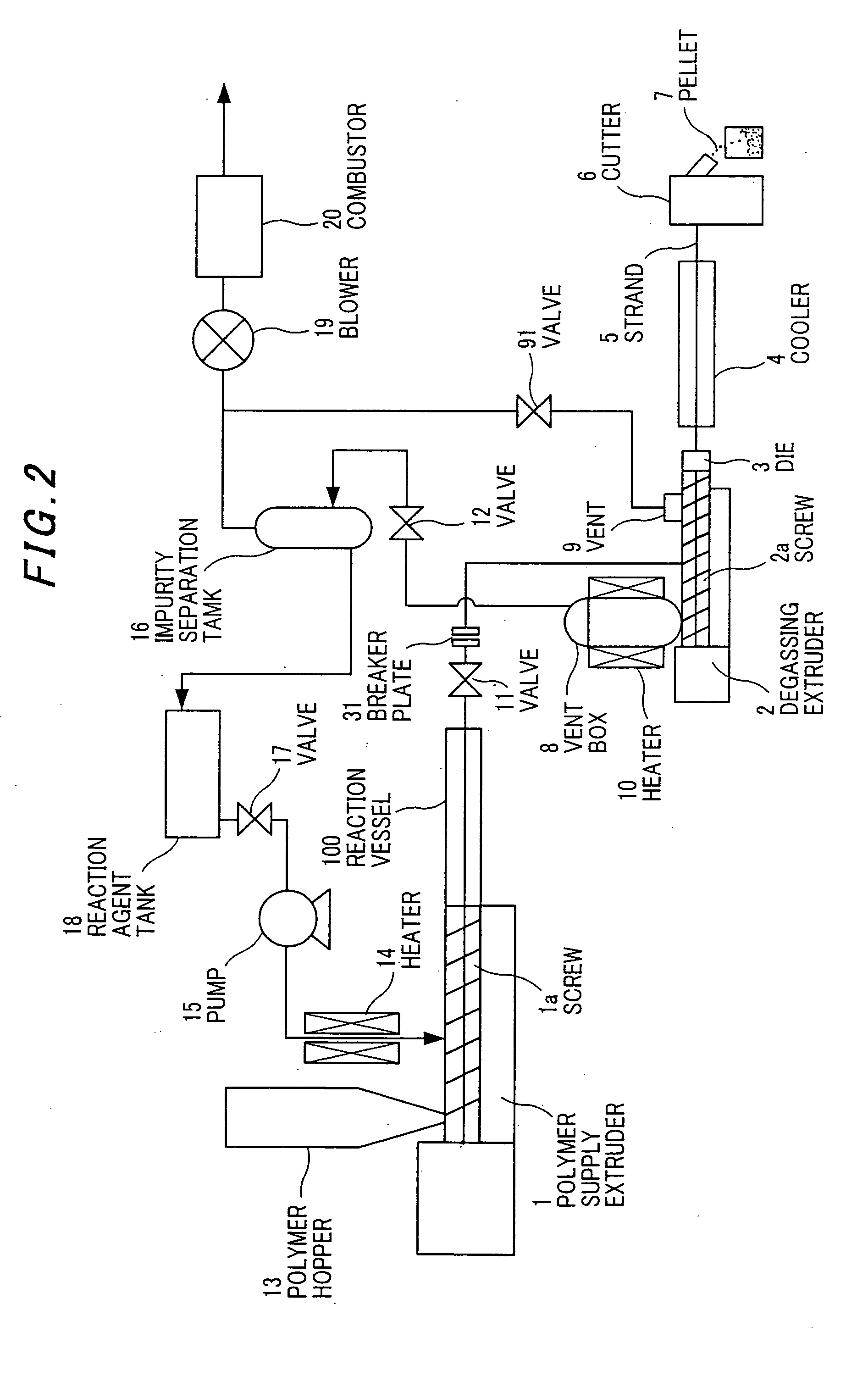
[0065]FIG. 1 is a flow diagram showing a cross-link cutting treatment apparatus for cross-linked polyethylene in the preferred embodiment of the invention.

[0066] Referring to FIG. 1, cross-linked polyethylene being pelletized is put through a hopper 13 in a polymer material supplying extruder 1 (cylinder diameter of 33 mm, L / D=50) . On the other hand, ethanol as a reaction agent necessary for the reaction is supplied from a reaction agent tank 18 through a valve 17 to the polymer material supplying extruder 1 while being compressed by a reaction agent supplying pump 15 and heated by a reaction agent heater 14. The supply position of reaction agent is desirably located downstream of a position where cross-linked polyethylene is sufficiently densified in the polymer material supplying extruder 1. Thereby, the reaction agent can be prevented from leaking toward upstream due to evaporation thereof.

[0067] The polymer material supplying extruder 1 uses a double-shaft extruder that has t...


PUM

PropertyMeasurementUnit
Pressureaaaaaaaaaa
Flow rateaaaaaaaaaa
Volumeaaaaaaaaaa

Abstract

A polymer treating method has the steps of: reacting a polymer compound with a reaction agent in a reaction vessel to generate a polymer treatment product; discharging the polymer treatment product containing the reaction agent from the reaction vessel; depressurizing the polymer treatment product; introducing the polymer treatment product into a degassing extruder; separating the reaction agent from the polymer treatment product through a vent box that is connected to upstream of the degassing extruder and that has a volume of equal to or more than that of the reaction vessel; and extruding the polymer treatment product from the degassing extruder.

Description

[0001] The present application is based on Japanese patent application No.2004-149230, the entire contents of which are incorporated herein by reference. BACKGROUND OF THE INVENTION [0002] 1. FIELD OF THE INVENTION [0003] The invention relates to a polymer treating method and a polymer treating apparatus that a polymer is processed into thermoplastic resin or wax by denaturalization or decomposition, or by cutting the cross-link point or molecular chain of cross-linked polymer, and more particularly to a polymer treating method and a polymer treating apparatus that a polymer is reacted with a reaction agent in supercritical state by using an extruder. [0004] 2. DESCRIPTION OF THE RELATED ART [0005] In recent years, as environment problems become important, the cost in disposal of wastage tends to increase. Regeneration or recycle of polymer is also desired. In this trend, the material recycle of thermoplastic resin is developed since it is possible to mold the thermoplastic resin ag...

Claims


Application Information

Patent Timeline
IPC IPC(8): C08J11/24B29C48/76C08G63/78C08J11/04
CPCC08J11/24Y02P20/582Y02W30/62
Inventor GOTO, TOSHIHARUYAMAZAKI, TAKANORI
Owner HITACHI METALS LTD
Learn More