Articulating tissue removal probe and methods of using the same

a technology of articulating tissue and probe, which is applied in the field of medical devices and methods for removing tissue, can solve the problems of disc tissue irreparably damaged, pain, and even prolonged disability, and limit the amount of tissue that can be removed to the tissue on the axis

Inactive Publication Date: 2005-11-24
BOSTON SCI SCIMED INC
View PDF37 Cites 149 Cited by
  • Summary
  • Abstract
  • Description
  • Claims
  • Application Information

AI Technical Summary

Benefits of technology

[0019] In accordance with a sixth aspect of the present inventions, the medical probe further comprises a drive shaft rotatably disposed within the probe shaft, in which case, the operative element will be mounted to the drive shaft. The drive shaft has a proximal rigid shaft portion associated with the proximal probe shaft portion, a distal rigid shaft portion associated with the distal probe shaft portion, and a linkage (e.g., a bellow, coil, U-joint, or beveled gear set) coupling the proximal and distal drive shaft portions. In this manner, the drive shaft may bend at the interface between the proximal and distal probe shaft portions without undergoing excessive stress.

Problems solved by technology

In some cases, however, the disc tissue is irreparably damaged, in which case, surgery is the best option.
VCFs are common in patients who suffer from these medical conditions, often resulting in pain, compromises to activities of daily living, and even prolonged disability.
Notably, such tissue removal probe is laterally constrained within the cannula (or if a cannula is not provided, constrained by the many layers of tissue that the device must traverse to reach the target tissue), and thus, can only be effectively moved along its longitudinal axis, thereby limiting the amount of tissue that can be removed to the tissue that is on-axis.
As can be appreciated, such technique increases the time of the spinal procedure as well as surgical risk.
However, use of a steering wire to bend a tissue removal probe may not provide sufficient rigidity for the probe to maintain its bent shape during use.
For example, during use, surrounding tissue at a target site may exert a force on the tissue removal probe, which causes the probe to unbent itself.
This in turn limits the range of target area which the tissue removal probe can reach.
The bend distal probe end, however, increases the profile of the probe, thereby requiring the access opening through which the probe is introduced into the patient to be increased, thereby increasing patient discomfort and recovery time.
In addition, the curvature of the bent distal end is fixed, thereby limiting access to the off-axis tissue.

Method used


Image

  • Articulating tissue removal probe and methods of using the same
  • Articulating tissue removal probe and methods of using the same
  • Articulating tissue removal probe and methods of using the same

Examples


Embodiment Construction

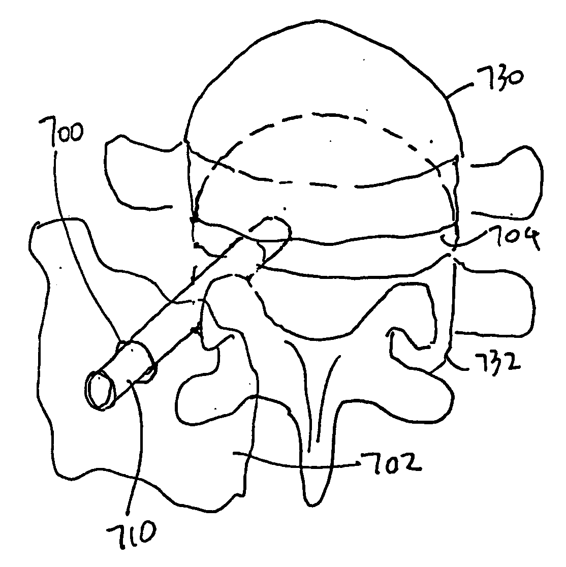
[0041]FIGS. 5A and 5B illustrate a tissue removal probe 100 constructed in accordance with one preferred embodiment of the present invention. The probe 100 includes a probe shaft 102 having a proximal probe shaft portion 104 that extends along a longitudinal axis 182, and a distal probe shaft portion 106 that extends along a longitudinal axis 180. In the illustrated embodiments, the proximal and the distal portions 104, 106 each has a longitudinal profile that is substantially rectilinear. Alternatively, either or both of the proximal and the distal portions 104, 106 can have a curvilinear or a bent configuration. The probe shaft portions 102 and 104 are rotatably coupled together at an interface. The proximal portion 104 of the probe shaft 102 includes a proximal end 110, a distal beveled end 112, and a lumen 118 extending between the proximal and distal ends 110, 112. The distal portion 106 of the probe shaft 102 includes a proximal beveled end 114, a distal end 116, and a lumen 1...


PUM


Abstract

A medical probe comprises a probe shaft having proximal and distal shaft portions, and an operative element, such as a tissue removal element, associated with the distal shaft portion. The proximal and distal shaft portions can be positioned relative to each other in an axially aligned relationship and an axially non-aligned relationship at the interface between the shaft portions. For example, the ends of the shaft portions that engage each other can be beveled, in which case, relative rotation of the shaft portions will cause the angle between the portions to vary. Or, the shaft portions can hinge relative to each other to vary the angle between them. Thus, it can be appreciated that the probe can be introduced along a straight path via a small opening within the patient, and then the probe shaft portions can be moved relative to each other to reach off-axis tissue. The probe may have a drive shaft that extends within the probe shaft and on which the operative element is mounted. The drive shaft may have proximal and distal rigid shaft portions and a linkage between the drive shaft portions, so that the drive shaft can bend when the probe shaft portions are placed in their axially non-aligned relationship.

Description

FIELD OF THE INVENTION [0001] The field of the invention pertains to medical devices and methods for removing tissue, and in particular, vertebral bone and intervertebral disc tissue. BACKGROUND OF THE INVENTION [0002] The spinal column consists of thirty-three bones called vertebra, the first twenty-four vertebrae of which make up the cervical, thoracic, and lumbar regions of the spine and are separated from each other by “pads” of tough cartilage called “intervertebral discs,” which act as shock absorbers that provide flexibility, stability, and pain-free movement of the spine. [0003]FIGS. 1 and 2 illustrate a portion of a healthy and normal spine, and specifically, two vertebra 10 and two intervertebral discs 12 (only one shown). The posterior of the vertebra 10 includes right and left transverse processes 14R, 14L, right and left superior articular processes 16R, 16L, and a spinous process 18. Muscles and ligaments that move and stabilize the vertebra 10 are connected to these s...

Claims


Application Information

Patent Timeline
Patent Type & Authority Applications(United States)
IPC IPC(8): A61B17/16A61B17/32
CPCA61B17/1631A61B17/1633A61B17/1671A61B2017/32004A61B2017/00261A61B2017/2927A61B2017/320032A61B17/32002
Inventor CARRISON, HAROLD F.NOVERO, LEONARD R.AGANON, NESTOR
Owner BOSTON SCI SCIMED INC
Why Eureka
Try Eureka