A method for manufacturing a propeller blade and a propeller blade

a manufacturing method and propeller technology, applied in the direction of machines/engines, soldering devices, turbines, etc., can solve the problems of severe damage to the blade, significant noise increase, and problem of the propeller blad

Active Publication Date: 2021-02-04
KONGSBERG MARITIME SWEDEN AB
View PDF0 Cites 1 Cited by
  • Summary
  • Abstract
  • Description
  • Claims
  • Application Information

AI Technical Summary

Benefits of technology

[0005]The object of the present invention is to meet the mentioned need and thus find a solution that is more reliable and cost-effective than known techniques.

Problems solved by technology

Propeller blades can suffer from the problem of cavitation adjacent the leading edge of the blade.
Cavitation will create a significantly increased noise spectrum, and a cavitation collapse process may cause severe damage to the blade and even destroy it.
Manufacturing the conduit is complicated due to the normally complex shape of the leading edge of a blade.
This procedure, however, leads to a risk of cracks in the region of the cover, in particular at the side thereof facing the leading edge.
These and other similar solutions thus also face disadvantages, and are also relatively costly.

Method used


Image

  • A method for manufacturing a propeller blade and a propeller blade
  • A method for manufacturing a propeller blade and a propeller blade
  • A method for manufacturing a propeller blade and a propeller blade

Examples


Embodiment Construction

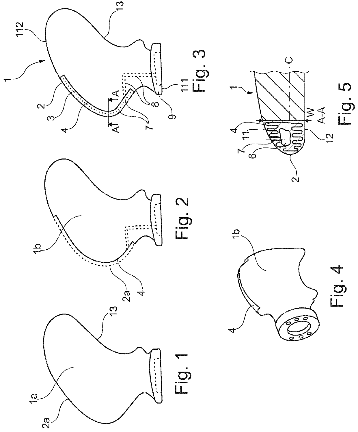
[0044]FIG. 1 in a side view illustrates a preliminary blank 1a for manufacturing a propeller blade according to an example of a way to carry out the invention. The preliminary blank 1a has a shape that substantially corresponds to the manufactured blade 1 (see FIG. 4). The preliminary blank 1a thus has a leading edge 2a substantially corresponding to the leading edge 2 of the manufactured blade 1. The preliminary blank also presents a trailing edge 13. It is understood that, as is known per se, the propeller blade presents the shapes of aerofoils extending along the intended fluid movement directions across the blade. As is known per se, the aerofoils present respective chord lines, (see FIG. 5, “C”), between the leading and trailing edges 2a, 13. On one side of the blade, a pressure side extends from the leading edge to the trailing edge, and on the other side of the blade, a suction side extends from the leading edge to the trailing edge.

[0045]The preliminary blank 1a may be produ...


PUM

PropertyMeasurementUnit
widthaaaaaaaaaa
volumeaaaaaaaaaa
shapeaaaaaaaaaa

Abstract

The present invention involves a method for manufacturing a blade (1) for a propeller, which blade (1) has a leading edge (2) and a trailing edge, the method comprising the steps of: forming a conduit in the blade (1), making a plurality of holes (7) through which the conduit (6) communicates with the exterior of the blade (1), and providing a blade blank having an edge part receiving surface (4) extending along at least a major part of the leading edge (2) of the blade (1) to be manufactured, wherein forming a conduit (6) comprises building up an edge part (3) onto the edge part receiving surface (4) by a wire-based additive manufacturing process, wherein the additive manufacturing process is adapted to form the conduit (6) at least partly delimited by the edge part (3) and extending along the leading edge (2) of the blade (1) to be manufactured.

Description

FIELD OF INVENTION[0001]The present invention relates to a method for manufacturing a blade for a propeller. The invention also relates to a blade for a propeller.BACKGROUND OF INVENTION[0002]Propeller blades can suffer from the problem of cavitation adjacent the leading edge of the blade. The cavitation normally takes place on the suction side or in the tip region of the blade. Cavitation will create a significantly increased noise spectrum, and a cavitation collapse process may cause severe damage to the blade and even destroy it. Many attempts have been made to cope with the cavitation problem. A used technique is to blow pressurized air to the region where cavitation is to be expected. According to a traditional technique this is achieved by providing a conduit within the blade, adjacent its leading edge. The conduit is, by a plurality of holes, connected to the suction, or to both sides of the blade, adjacent the leading edge. The conduit is, by means of a supply duct through t...

Claims


Application Information

Patent Timeline
Patent Type & Authority Applications(United States)
IPC IPC(8): B64C11/26F01D5/14F01D5/18
CPCB64C11/26B33Y10/00F01D5/18F01D5/141B23K26/34B23K2101/001B33Y80/00F05D2240/303B63H1/26B63H1/18Y02P10/25F01D5/286B23K35/0261F01D5/14F01D5/28F05D2230/30F05D2230/31B23P15/00B23P15/04
Inventor KRON, PATRIK
Owner KONGSBERG MARITIME SWEDEN AB
Why Eureka
Try Eureka