
DLL phase detection using advanced phase equal

a phase equalization and phase detection technology, applied in the field of synchronous circuits, can solve the problems of significantly slowing down the establishment of lock points, wasting dll time, and wasting dll time, and achieve the effect of fasting up the dll locking tim

Active Publication Date: 2005-11-24
MICRON TECH INC
View PDF63 Cites 31 Cited by
  • Summary
  • Abstract
  • Description
  • Claims
  • Application Information

AI Technical Summary

Benefits of technology

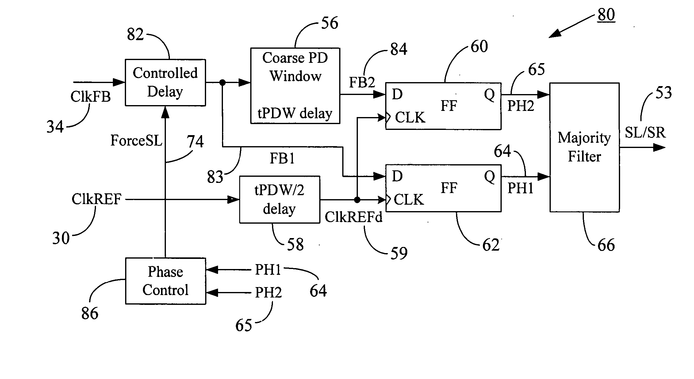
[0037] The system and method of the present disclosure generate and terminate clock shift modes during initialization of a synchronous circuit (e.g., a delay-locked loop or DLL). Upon initialization, the DLL is entered into a ForceSL (Force Shift Left) mode and an On1x mode (i.e., left shifting on each clock cycle). The feedback clock that tracks the phase of the reference clock (which, in turn, is derived from the system clock) is initially delayed in a coarse phase detector prior to applying it to the coarse phase detection window. Two delayed versions of the feedback clock are sampled by the reference clock to generate a pair of phase information signals, which are then used to establish an advanced phase equal (APHEQ) signal. The APHEQ signal advances onset of the PHEQ (phase equalization) phase and is used to terminate the ForceSL and On1x modes, thereby preventing wrong ForceSL exit due to clock jitter or feedback path overshooting during On1x exit. The avoidance of wrong ForceSL exit and On1x overshooting problems further results in faster DLL locking time.

Problems solved by technology

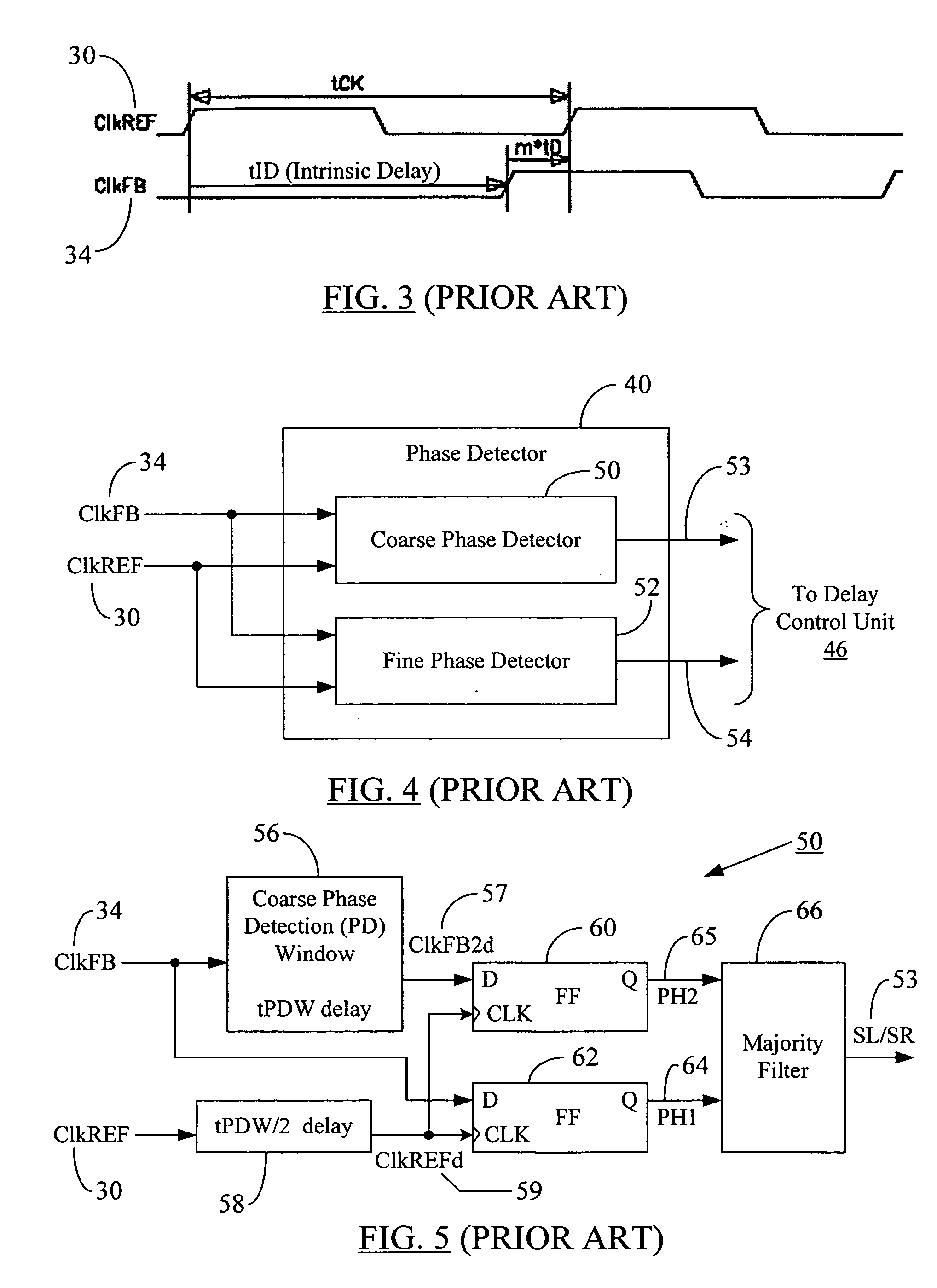
Such counting may consume time and delay the shifting of the Ref clock 30 and, hence, may delay the establishment of the lock as discussed in detail later hereinbelow.
Hence, the use of majority filter 66 during initialization may significantly slow down the lock point establishment.
This results in the overshooting illustrated in FIG. 12, which not only disrupts the phase alignment between ClkREF and ClkFB, but also further slows the lock establishment time by adding extra delays to establish lock.
However, as discussed in the preceding paragraph, if the On1x mode is continued after ForceSL mode ends (as shown in FIG. 12), the problem of overshooting on the feedback path may occur, especially when tFB>1*tCK (tFB=4tCK for the waveforms in FIG. 12), which is quite common in modern high speed system and reference clocks.
However, at long tCK (slower clock frequencies) and short tID, the clock jitter may cause the ForceSL mode to exit prematurely as shown through the waveforms in FIG. 14.
However, as discussed before with reference to FIG. 12, when the On1x mode is exited after the ForceSL mode, the problem of overshooting in the feedback path may occur, especially at higher frequencies.
It is observed here that the wrong ForceSL exit problem may be solved using an appropriate filter, but the On1x overshooting problem may still remain.

Method used


Image

  • DLL phase detection using advanced phase equal
  • DLL phase detection using advanced phase equal
  • DLL phase detection using advanced phase equal

Examples


Embodiment Construction

[0058] Reference will now be made in detail to some embodiments of the present disclosure, examples of which are illustrated in the accompanying drawings. It is to be understood that the figures and descriptions of the present disclosure included herein illustrate and describe elements that are of particular relevance to the present disclosure, while eliminating, for the sake of clarity, other elements found in typical solid-state memories or memory-based systems. It is noted at the outset that the terms “connected”, “connecting,”“electrically connected,” etc., are used interchangeably herein to generally refer to the condition of being electrically connected. It is further noted that various block diagrams, circuit diagrams and timing waveforms shown and discussed herein employ logic circuits that implement positive logic, i.e., a high value on a signal is treated as a logic “1” whereas a low value is treated as a logic “0.” However, any of the circuit discussed herein may be easil...


PUM


Abstract

A system and method are disclosed to generate and terminate clock shift modes during initialization of a synchronous circuit (e.g., a delay-locked loop or DLL). Upon initialization, the DLL is entered into a ForceSL (Force Shift Left) mode and an On1x mode (i.e., left shifting on each clock cycle). The feedback clock that tracks the phase of the reference clock (which, in turn, is derived from the system clock) is initially delayed in a coarse phase detector prior to applying it to the coarse phase detection window. Two delayed versions of the feedback clock are sampled by the reference clock to generate a pair of phase information signals, which are then used to establish an advanced phase equal (APHEQ) signal. The APHEQ signal advances onset of the PHEQ (phase equalization) phase and is used to terminate the ForceSL and On1x modes, thereby preventing wrong ForceSL exit due to clock jitter or feedback path overshooting during On1x exit. The avoidance of wrong ForceSL exit and On1x overshooting problems further results in faster DLL locking time.

Description

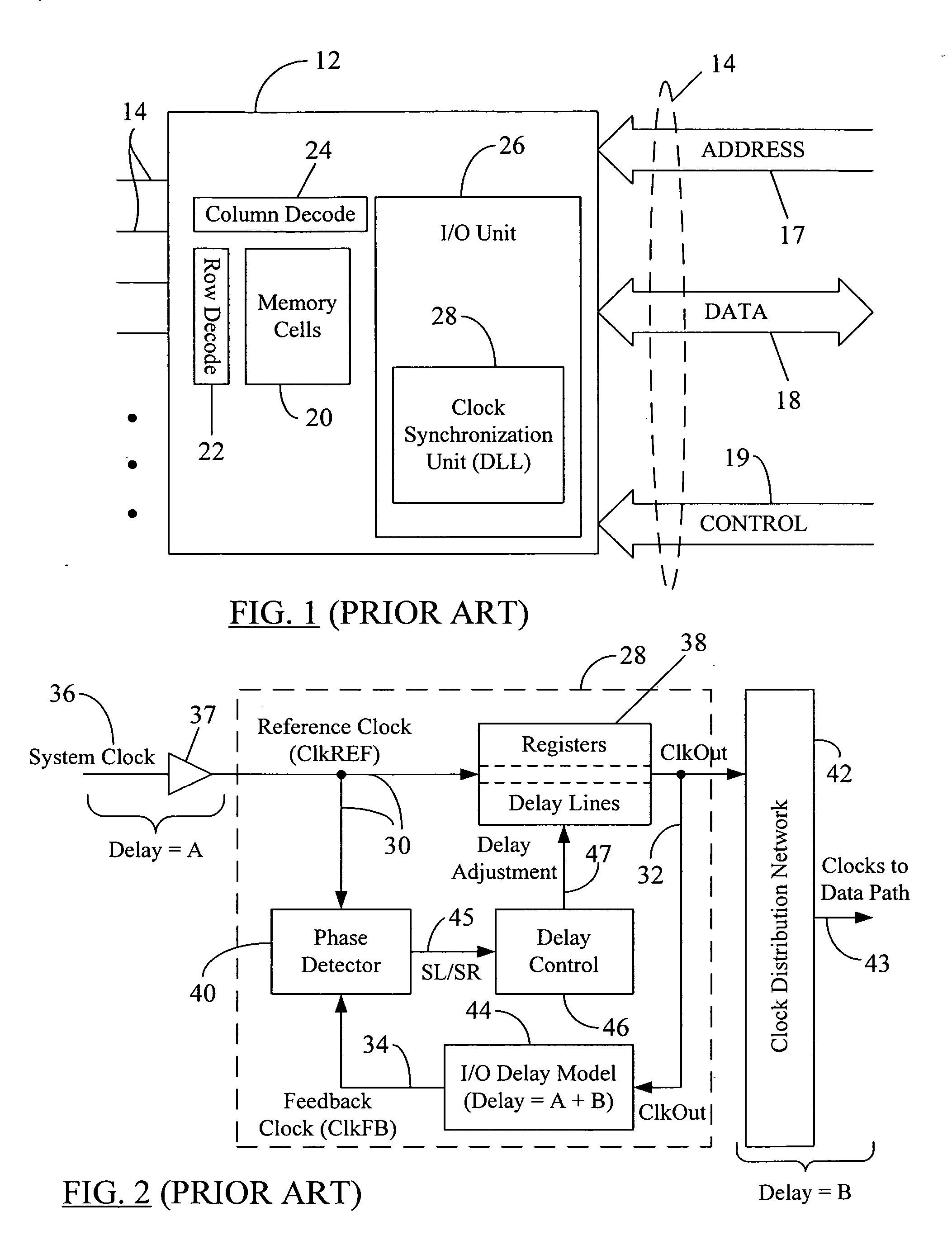
REFERENCE TO RELATED APPLICATION [0001] The disclosure in the present application is related to the disclosure provided in the commonly-assigned U.S. patent application Ser. No. 09 / 652,364, titled “A Phase Detector for All-Digital Phase Locked and Delay Locked Loops”, filed on Aug. 31, 2000.BACKGROUND [0002] 1. Field of the Disclosure [0003] The present disclosure generally relates to synchronous circuits and, more particularly, to a system and method to generate and terminate clock shift modes during initialization of a synchronous circuit. [0004] 2. Brief Description of Related Art [0005] Most digital logic implemented on integrated circuits is clocked synchronous sequential logic. In electronic devices such as synchronous dynamic random access memory circuits (SDRAMs), microprocessors, digital signal processors, etc., the processing, storage, and retrieval of information is coordinated or synchronized with a clock signal. The speed and stability of the clock signal determines to ...

Claims


Application Information

Patent Timeline
IPC IPC(8): H03L7/081H03L7/085
CPCH03L7/085H03L7/0814H03L7/0816H03L7/081H03L7/00
Inventor KIM, KANG YONG
Owner MICRON TECH INC
Learn More