
Method for producing a pressure sensor for detecting small pressure differences and low pressures

Inactive Publication Date: 2005-12-01
MKS INSTR INC
View PDF30 Cites 30 Cited by
  • Summary
  • Abstract
  • Description
  • Claims
  • Application Information

AI Technical Summary

Benefits of technology

[0009] It is an object of the invention to provide sensor elements which have an extremely high sensitivity and stability, and which can stand large pressure variations.
[0010] A sensor element of the capacitive type constructed of mainly ceramic materials comprises a circular ceramic plate, also called a diaphragm, which is movable with the pressure of the gas acting on it and which is extremely thin and has typically a thickness less than 0.1 mm for a diameter of 38 mm of the plate, i.e., it has a ratio of the thickness to the diameter which is less than substantially 0.26%. The ratio of the thickness to the diameter of the movable portion of the diaphragm will then be less than about 0.35%. As to its other characteristics the sensor element can be made according to the disclosure of the published International patent application W098 / 37392. The extremely thin ceramic diaphragm is furthermore attached between two ceramic elements in a particular manner. Such a mounting allows that the sensor element can be made to have an insignificant temperature drift.

Problems solved by technology

Other ceramic materials, such as glass ceramic materials, can also be used but do not have equally good properties.

Method used


Image

  • Method for producing a pressure sensor for detecting small pressure differences and low pressures
  • Method for producing a pressure sensor for detecting small pressure differences and low pressures
  • Method for producing a pressure sensor for detecting small pressure differences and low pressures

Examples


Embodiment Construction

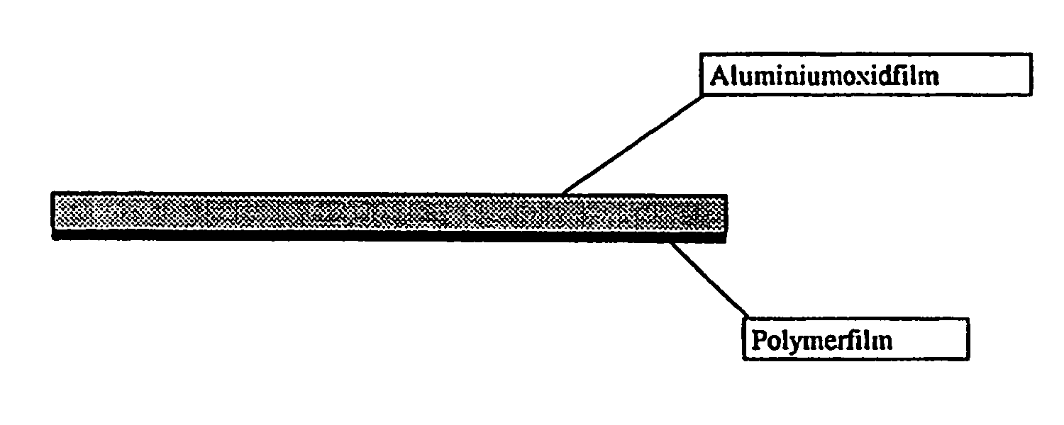
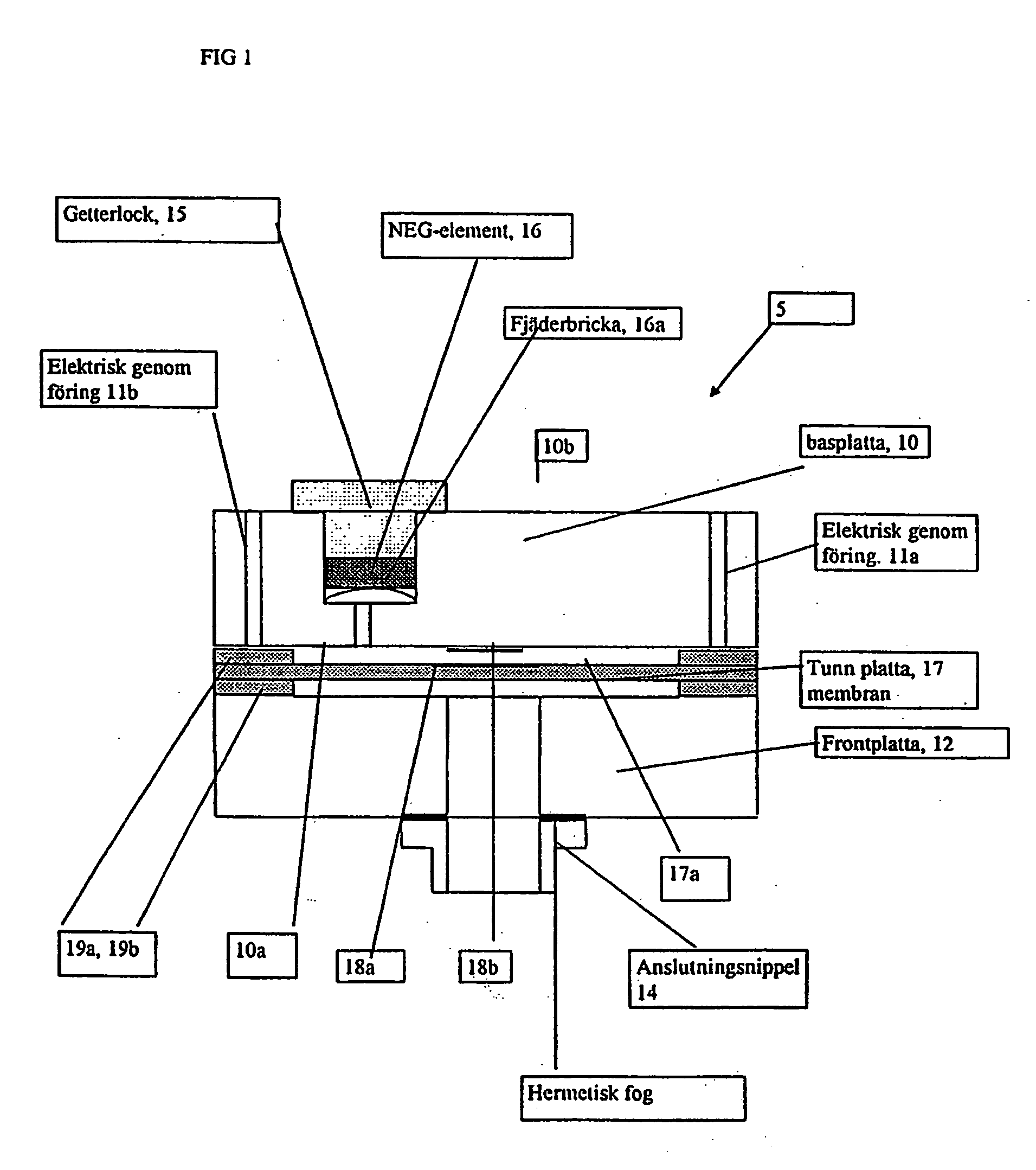
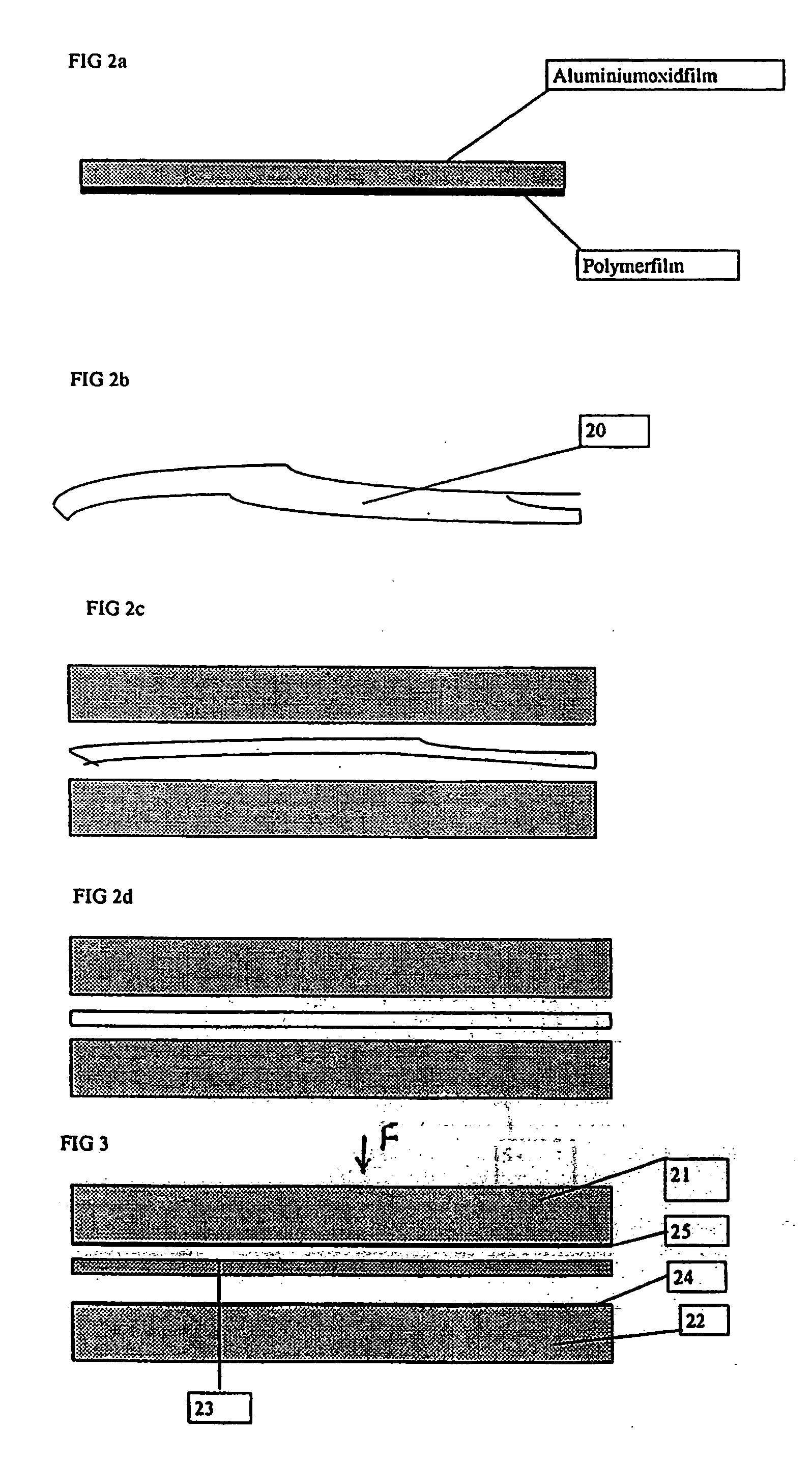
[0034] Sensor elements of the absolute type, i.e., for measuring absolute pressures, according to Case A as defined above consist of three ceramic circular plates. In FIG. 1 such a sensor element 5 is shown, which is built of a base plate 10, a front plate 12 and a circular ceramic plate 17, also called a diaphragm, which is movable with the difference of the gas pressures acting on its large surfaces. The diaphragm is extremely thin in relation to its diameter and is located between the base plate and the front plate. In the base plate 10, two circular through-holes 11a and 11b are provided for letting electrical conductors through. On the under side 10a of the base plate 10 an electrically conducting thin film 18b of preferably gold is provided, which is made by means of thin film methods, the free, under surface of this thin film 18b constituting one of two opposite electrically conductive areas which form the measurement capacitor of the sensor element. On the top surface 17a of...


PUM


Abstract

A process for producing a plate for a capacitive sensor element. In one embodiment of the present invention, a method includes forming a plate from a substantially pure aluminum oxide slurry, heating the plate a first time in an oven to sinter the plate, cooling the plate after the heating step, heating the plate a second time to smooth the plate, and cooling the plate after the second heating.

Description

RELATED APPLICATIONS [0001] This patent application is a divisional patent application of U.S. Ser. No. 10 / 642,106, filed Aug. 15, 2003, which is a continuation application of U.S. Ser. No. 09 / 582,057, filed Oct. 23, 2000, which claims priority to PCT application PCT / SE98 / 02441, filed Dec. 22, 1998, which claims priority to Sweden application 9704840-9, filed Dec. 22, 1997, all of which are hereby incorporated herein by reference.TECHNICAL FIELD [0002] The present invention relates to a ceramic, capacitive pressure transducer or sensor element for detecting small pressure differences and low pressures. BACKGROUND [0003] Sensor elements to be used in pressure sensors can be designed to detect strain or capacitance, i.e. be the strain type or the capacitive type. They can be built from various ceramic materials. Ceramic materials based on aluminium oxide are often used in such sensor elements, but glass ceramic materials can also be used. A ceramic capacitive sensor element for sensin...

Claims


Application Information

Patent Timeline
IPC IPC(8): G01L9/00G01L13/02
CPCG01L9/0073G01L13/025G01L9/0075
Inventor JONSSON, STAFFAN
Owner MKS INSTR INC
Learn More