Diverter valve with multiple valve seat rings

a diverter valve and seat ring technology, applied in the direction of transportation and packaging, process and machine control, instruments, etc., can solve the problems of valve element impact load, non-vented fluidic amplifiers may not provide 100% flow diversion, suffer certain drawbacks, etc., to reduce the impact stress on the valve element and increase the life of the valve element.

Inactive Publication Date: 2005-12-01
HONEYWELL INT INC
View PDF12 Cites 25 Cited by
  • Summary
  • Abstract
  • Description
  • Claims
  • Application Information

AI Technical Summary

Benefits of technology

[0007] The present invention provides a hot gas diverter valve with multiple valve seats. The multiple valve seat configuration reduces the impact stress on the valve element during valve operations, and thus increases valve element lifetime, as compared to present diverter valves.

Problems solved by technology

However, non-vented fluidic amplifiers may not provide 100% flow diversion.
Although the above-described type of diverter valve is robustly designed and manufactured, and operates safely, it suffers certain drawbacks.
However, the relatively small contact area can, in many instances, result in the valve element experiencing an impact load during operation that is concentrated on a relatively small area of the valve element.
This concentrated impact load can damage the valve element, which can adversely impact system performance, shorten valve element lifetime, and / or reduce overall system reliability.

Method used


Image

  • Diverter valve with multiple valve seat rings
  • Diverter valve with multiple valve seat rings
  • Diverter valve with multiple valve seat rings

Examples


Embodiment Construction

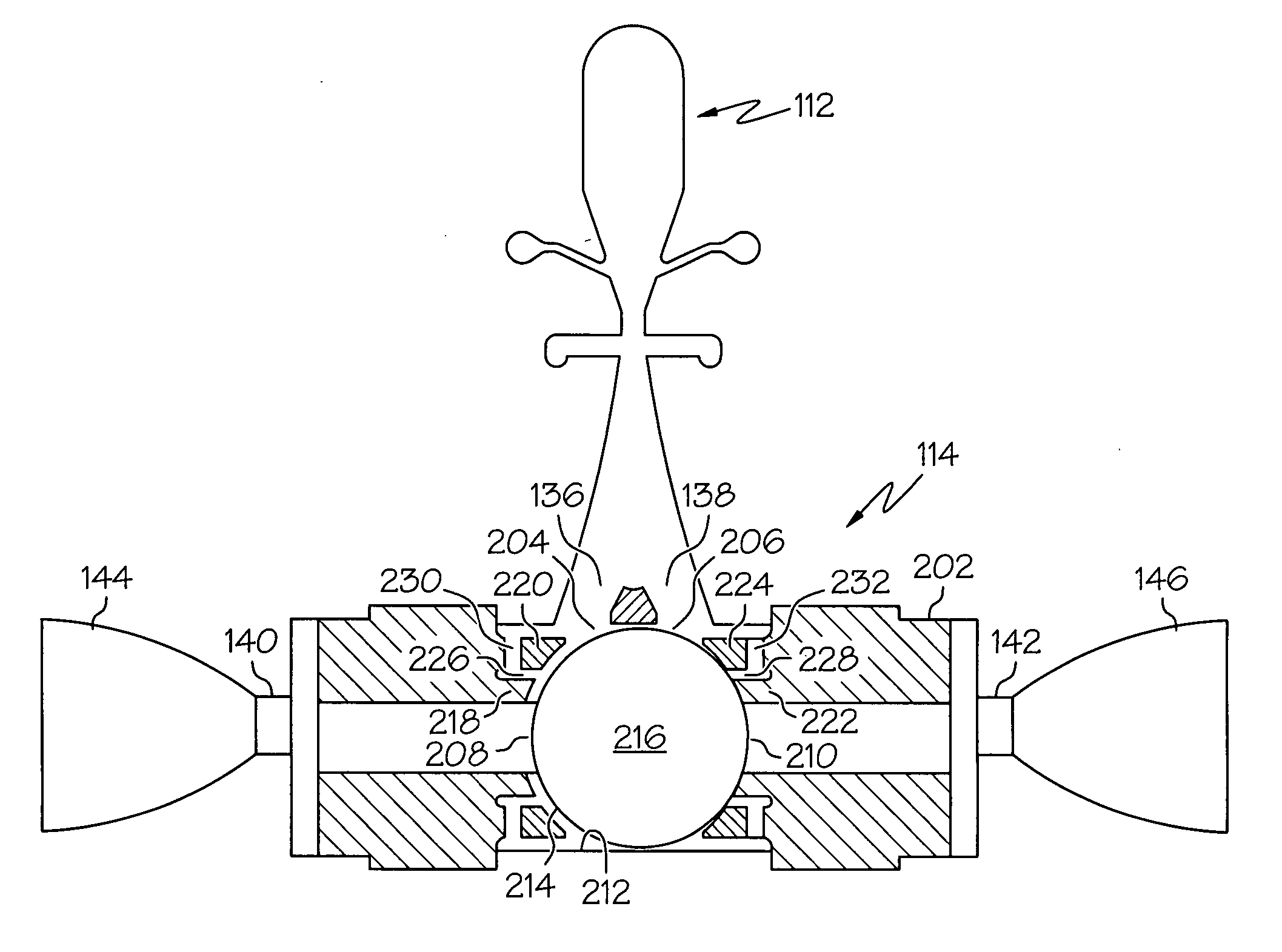
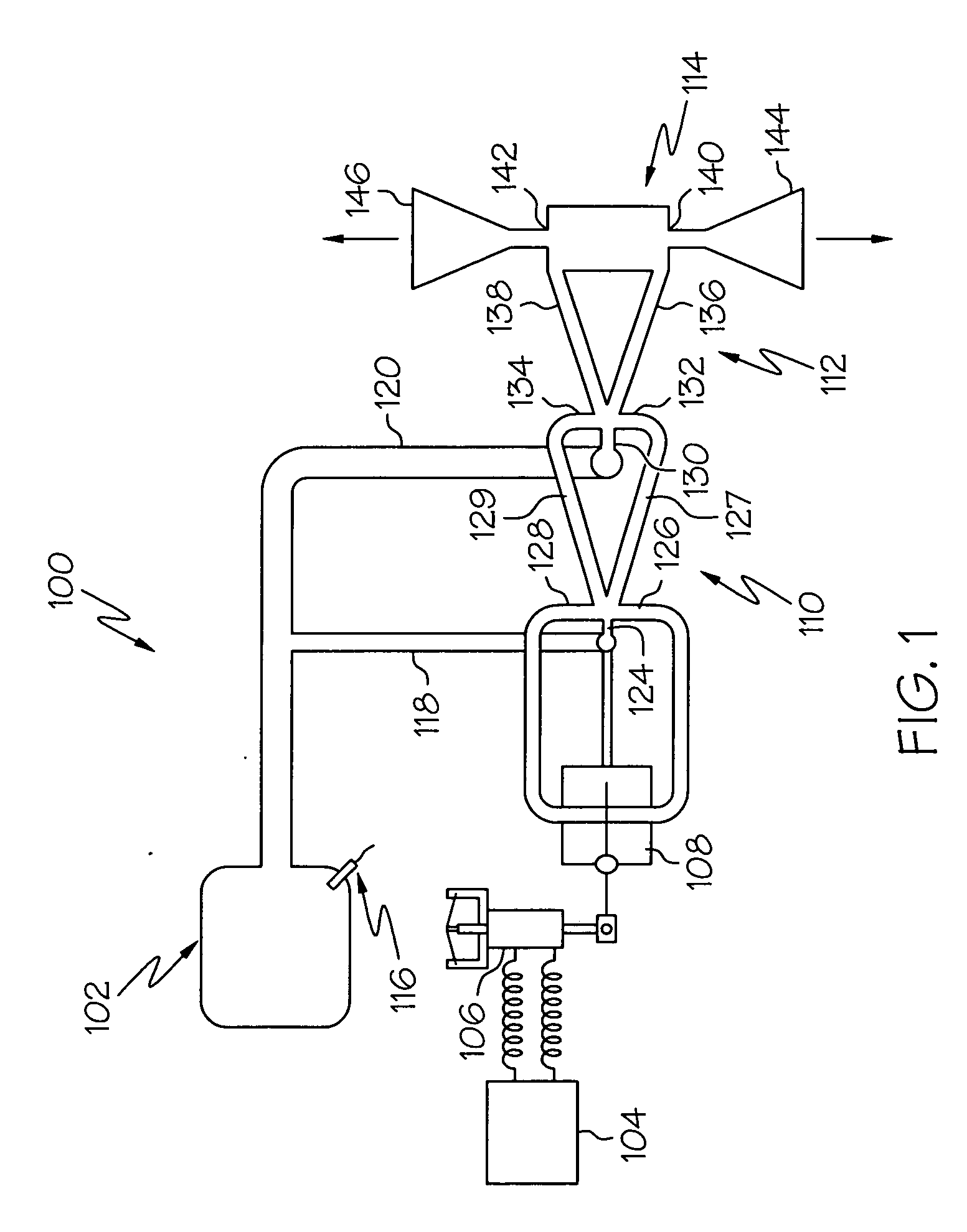
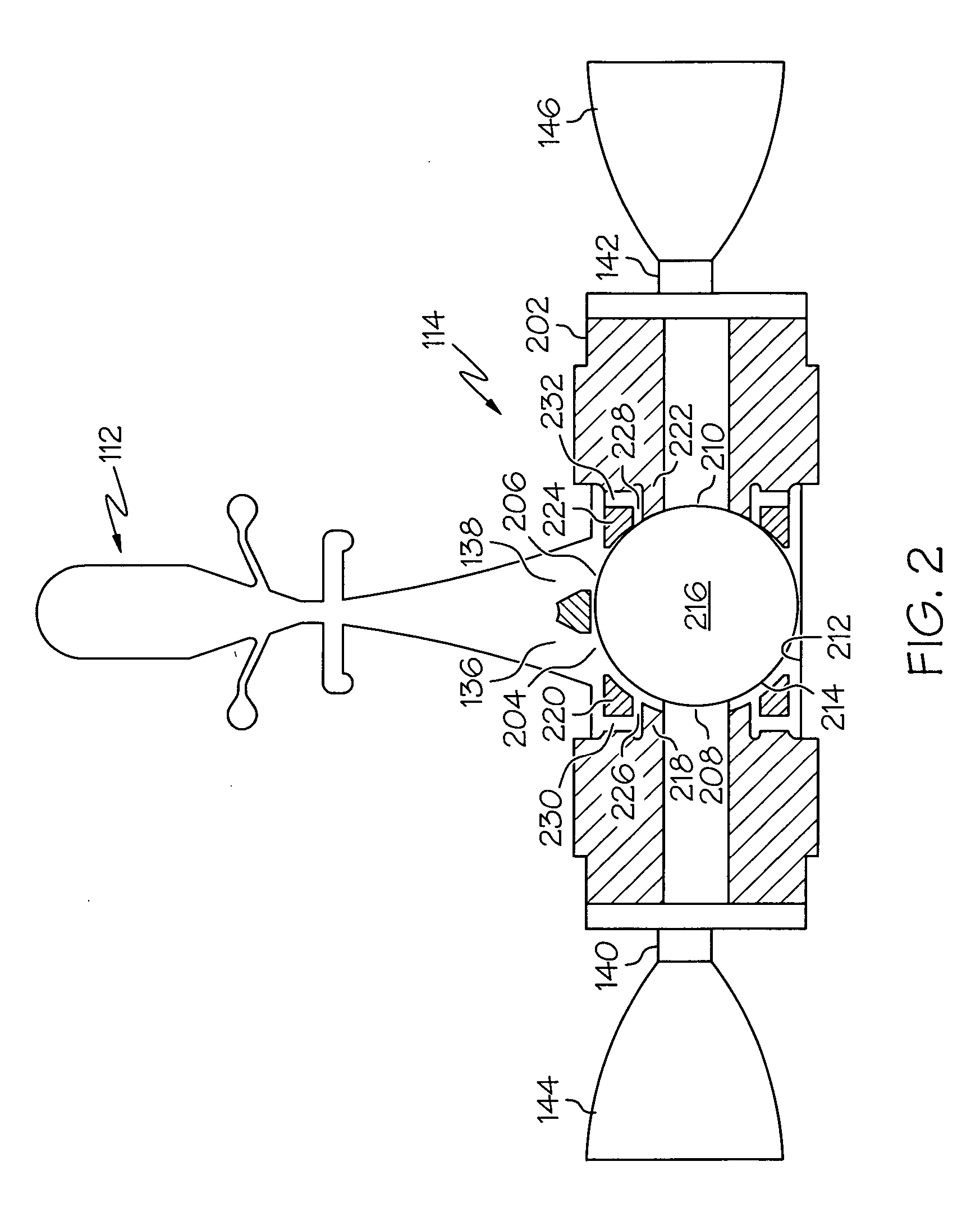
[0014] A simplified schematic diagram of at least a portion of an exemplary flight control system 100 that may use an embodiment of the present invention is illustrated in FIG. 1. The system 100 includes a gas generator 102, a flight controller 104, a solenoid valve 106, a pilot valve 108, a first stage fluidic amplifier 110, a second stage fluidic amplifier 112, and a diverter valve 114. The gas generator 102 includes initiators 116 that, during a vehicle launch sequence or at some point during vehicle flight, activates the gas generator 102. The gas generator 102, upon activation, supplies a flow of high pressure, high temperature gas to one or more gas flow paths. In the depicted embodiment, a first gas flow path 118 is fluidly coupled to the first stage fluidic amplifier 110 and to the pilot valve 108, and a second gas flow path 120 is fluidly coupled to the second stage fluidic amplifier 112.

[0015] The first 110 and second 112 stage fluidic amplifiers are each preferably non-v...


PUM


Abstract

A diverter valve includes a valve bore having a set of valve seats associated with each fluid outlet port. Each set of valve seats is at least partially separated from one another by a flow channel. The valve seat configuration increases the impact area for the valve element. As a result, the impact force upon seating against the valve seats is reduced. Moreover, by including flow channels between the sets of valve seats, the switching force and performance of the valve element is not adversely affected.

Description

FIELD OF THE INVENTION [0001] The present invention relates to hot gas diverter valves used in missile and spacecraft propulsion systems and, more particularly, to a hot gas diverter valve having multiple valve seat rings. BACKGROUND OF THE INVENTION [0002] The movements involved in flight of some missiles and space vehicles, such as pitch, yaw, and spin rate, are controlled with flight control systems that use reaction jets. In some systems of this type, a pressurized gas source, such as a gas generator, supplies a pressurized gas to one or more fluidic amplifier stages. In response to a control signal supplied from flight control equipment, a fluidic amplifier stage can selectively divert the pressurized gas into one of two or more flow paths. Each flow path may have a nozzle on its outlet that is located external to the missile or vehicle. These nozzles may be positioned to provide thrust in different or opposite directions. Thus, the fluidic amplifier stages can affect one or mo...

Claims


Application Information

Patent Timeline
Patent Type & Authority Applications(United States)
IPC IPC(8): F15B13/043F15C1/00F15C1/08F15C1/12
CPCF15B13/0436F15C1/08F15C1/006F15B13/0438Y10T137/2147Y10T137/2213Y10T137/2218Y10T137/2567Y10T137/2663Y10T137/87788
Inventor TSENG, RAYMOND R.LARSEN, BRUCE
Owner HONEYWELL INT INC
Why Eureka
Try Eureka