Nozzle checker for laser beam machine

a laser beam machine and checker technology, applied in laser beam welding apparatus, optically investigating flaws/contamination, manufacturing tools, etc., can solve the problems of generating dross, difficult to maintain a fixed clearance between the tip of the nozzle and the top face of the workpiece in a stable manner, and machining defects. , to achieve the effect of high machining quality and high machining quality

Inactive Publication Date: 2005-12-01
YAMAZAKI MAZAK KK
View PDF25 Cites 9 Cited by
  • Summary
  • Abstract
  • Description
  • Claims
  • Application Information

AI Technical Summary

Benefits of technology

[0016] According to the present invention, since the out-of-roundness of the nozzle is always kept within tolerances, the flow velocity distribution of jets of assist gas is not disturbed and high machining quality can be maintained.
[0017] Furthermore, since the nozzle tip is kept free of foreign matter, dents, etc., it is possible to maintain a fixed clearance between the tip of the nozzle and top face of the workpiece in a stable manner and thus maintain high machining quality.
[0018] This allows even an unskilled operator to perform high-quality, high-precision machining and even enables continuous unattended operation.

Problems solved by technology

When laser machining is continued under standard machining conditions, abnormalities of the nozzle attached to the tip of the machining torch can cause machining defects such as generation of dross.
Any foreign matter attached to the nozzle of the laser beam machine makes it difficult to maintain a fixed clearance between the tip of the nozzle and top face of the workpiece in a stable manner.
This will cause machining defects such as degradation of machining quality or even disable machining.
Also, any foreign matter attached to the nozzle tip can cause an outlet in the nozzle tip to go out of round, disturbing flow velocity distribution of jets of assist gas.
This will cause machining defects such as degradation of machining quality or even disable machining.
To avoid the above problems and maintain optimum machining is something an unskilled operator cannot accomplish and requires a skilled operator with many years of experience.
This has hindered continuous unattended operation from being implemented.

Method used


Image

  • Nozzle checker for laser beam machine
  • Nozzle checker for laser beam machine
  • Nozzle checker for laser beam machine

Examples


Embodiment Construction

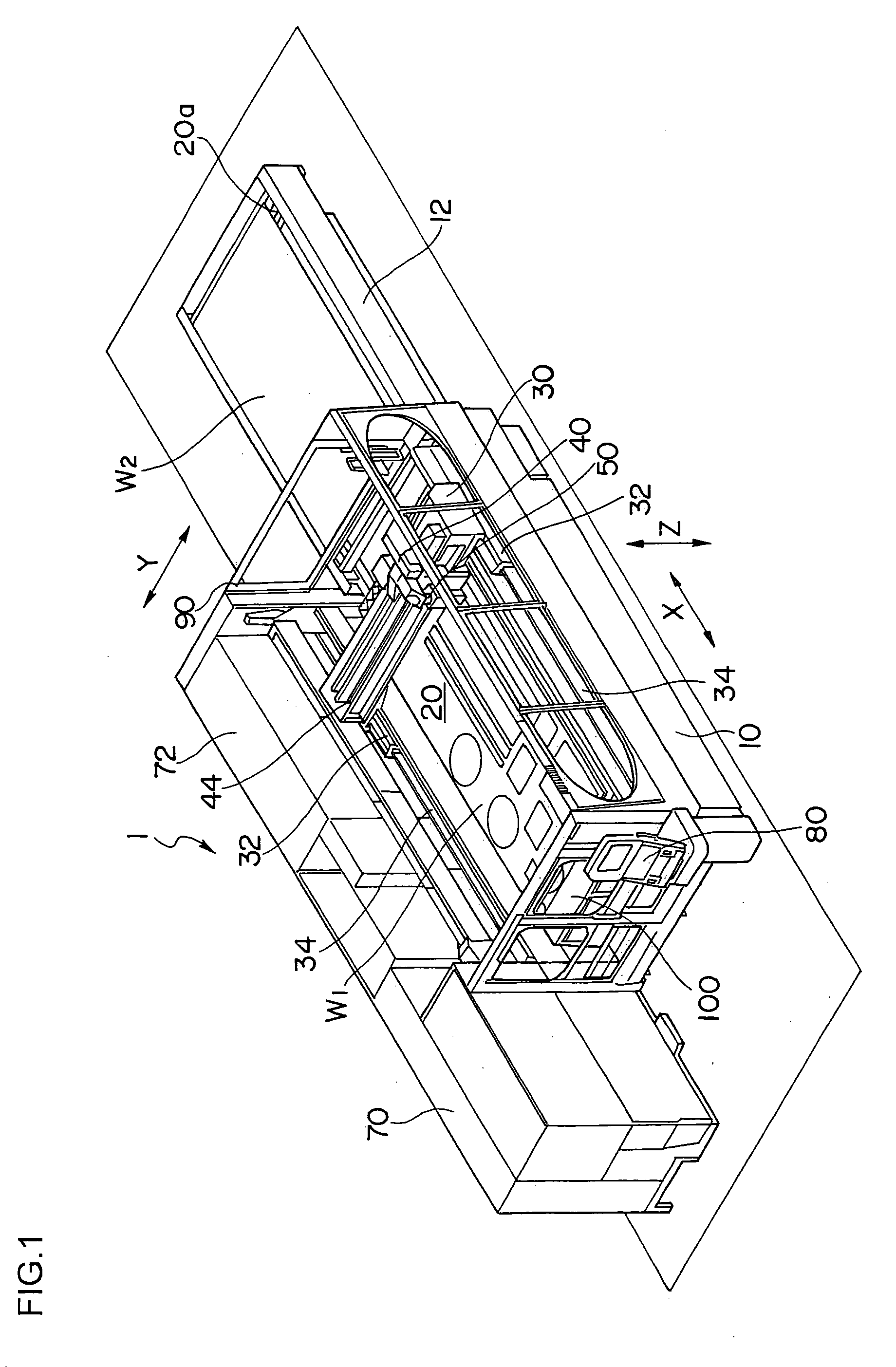
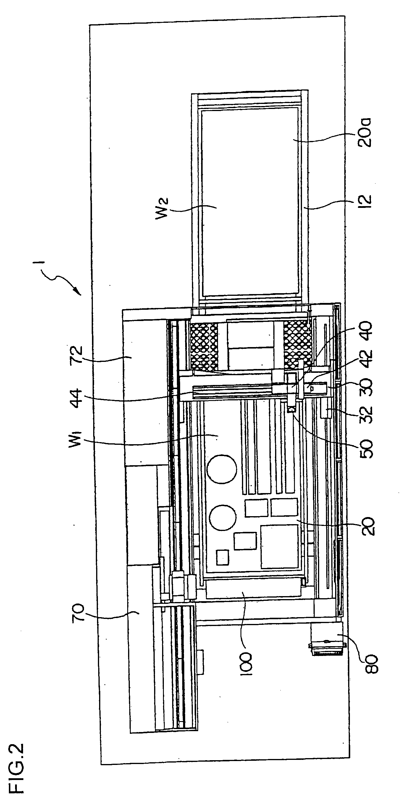
[0033]FIG. 1 is a perspective view showing an overall configuration of a laser beam machine according to the present invention, FIG. 2 is a plan view, FIG. 3 is a front view, FIG. 4 is a perspective view of the relevant portion, and FIG. 5 is a side view.

[0034] A laser beam machine, generally denoted by reference number 1, has a pallet (table) 20 which is disposed on a bed 10 to carry a plate-shaped workpiece W1. A pallet changer 12 is placed on the longitudinal extension of the bed 10, and a pallet 20a carrying a workpiece W2 to be machined next is awaiting its turn.

[0035] A pair of guide rails 34 are installed on both sides of the bed 10 along its length and a column 30 is mounted on the guide rails 34 in such a way as to be movable along an X axis.

[0036] Means for driving the column 30 along the X axis is provided by, for example, a linear motor, which is formed by a stator installed on the guide rails 34 and a moving member installed on a linear-motion guide 32.

[0037] A guid...


PUM

PropertyMeasurementUnit
thicknessaaaaaaaaaa
flow velocity distributionaaaaaaaaaa
lengthaaaaaaaaaa

Abstract

The invention provides a device which optically checks a nozzle tip of a laser machining tool. A camera unit 450 which is raised and lowered in opposing relation to a nozzle 65 of a laser beam machine has a camera chamber 454 and is sealed by protective glass 456, where the camera chamber 454 contains a CCD camera body 460 and lens 462. While a ring light 470 illuminates a surface of the nozzle 65, the CCD camera body 460 checks the nozzle 65 optically.

Description

[0001] The present application is based on and claims priority of Japanese patent application No. 2004-155930 filed on May 26, 2004, the entire contents of which are hereby incorporated by reference. BACKGROUND OF THE INVENTION [0002] 1. Field of the Invention [0003] The present invention relates to a device which checks the shape of a nozzle tip of a laser beam machine for any abnormality (foreign matter, deformation, or tip flaws) using a shape / property recognition device such as a camera. [0004] 2. Description of the Related Art [0005] In the case of conventional laser beam machines, predetermined standard machining conditions are registered with an NC system according to material and workpiece thickness. [0006] When laser machining is continued under standard machining conditions, abnormalities of the nozzle attached to the tip of the machining torch can cause machining defects such as generation of dross. To maintain optimum machining conditions, conventionally the operator has...

Claims


Application Information

Patent Timeline
Patent Type & Authority Applications(United States)
IPC IPC(8): B23K26/00B23K26/064B23K26/08
CPCB23K26/0884B23K26/422B23K26/1494B23K26/1482B23K26/043B23K26/702G01N21/94
Inventor YAMAZAKI, TSUNEHIKOMIYAKAWA, NAOOMI
Owner YAMAZAKI MAZAK KK
Why Eureka
Try Eureka