
Imprinting method, information recording medium-manufacturing method, and imprinting apparatus

a technology of information recording medium and imprinting method, which is applied in the field of imprinting method and imprinting apparatus, can solve the problems of deformation or incompleteness, conventional imprinting method, and substrate damage (crack), and achieve the effect of reducing temperature changes, reducing shrinkage difference, and reducing deformation

Inactive Publication Date: 2005-12-01
TDK CORPARATION
View PDF5 Cites 19 Cited by
  • Summary
  • Abstract
  • Description
  • Claims
  • Application Information

AI Technical Summary

Benefits of technology

The present invention provides an improved imprinting method and apparatus for forming a concave / convex pattern on a substrate. The method and apparatus involve heating the resin layer and pressing a stamper against it, followed by rapidly removing the stamper while maintaining the temperature of the resin layer. This process prevents deformation or incompletness of the pattern and allows for faster production of intermediates for information recording media. The main technical effects of the invention are the prevention of deformation or incompletness of the pattern and the shortening of the cooling process.

Problems solved by technology

As a result of the study of the conventional imprinting method, however, the present inventors found the following problems: In the imprinting method, both of the laminate of the substrate and the resin layer, and the stamper are heated to approximately 200° C. when the stamper is pressed against the resin layer, and cooled to room temperature before the stamper is removed from the resin layer.
For this reason, the conventional imprinting method suffers from the problem of possibility of deformation or incompleteness of a concave / convex pattern formed on the substrate.
In this case, if the laminate and the stamper are rapidly cooled, there is a fear that the substrate is damaged (cracked) due to the rapid decrease in temperature.
For this reason, the conventional imprinting method suffers from the problem that it takes a relatively long time to form the concave / convex pattern.

Method used


Image

  • Imprinting method, information recording medium-manufacturing method, and imprinting apparatus
  • Imprinting method, information recording medium-manufacturing method, and imprinting apparatus
  • Imprinting method, information recording medium-manufacturing method, and imprinting apparatus

Examples


Embodiment Construction

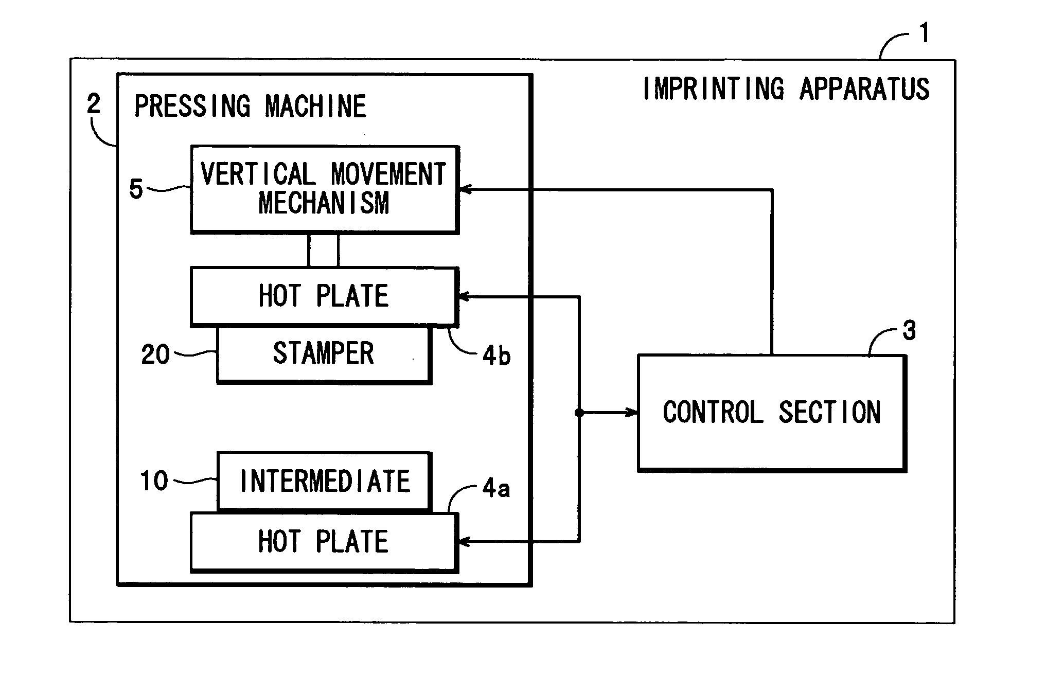
[0035] Hereafter, an imprinting method, a method of manufacturing an information recording medium, and an imprinting apparatus, according to a preferred embodiment of the present invention, will be described with reference to the accompanying drawings.

[0036] First, a description will be given of the arrangement of the imprinting apparatus 1 according to the present invention.

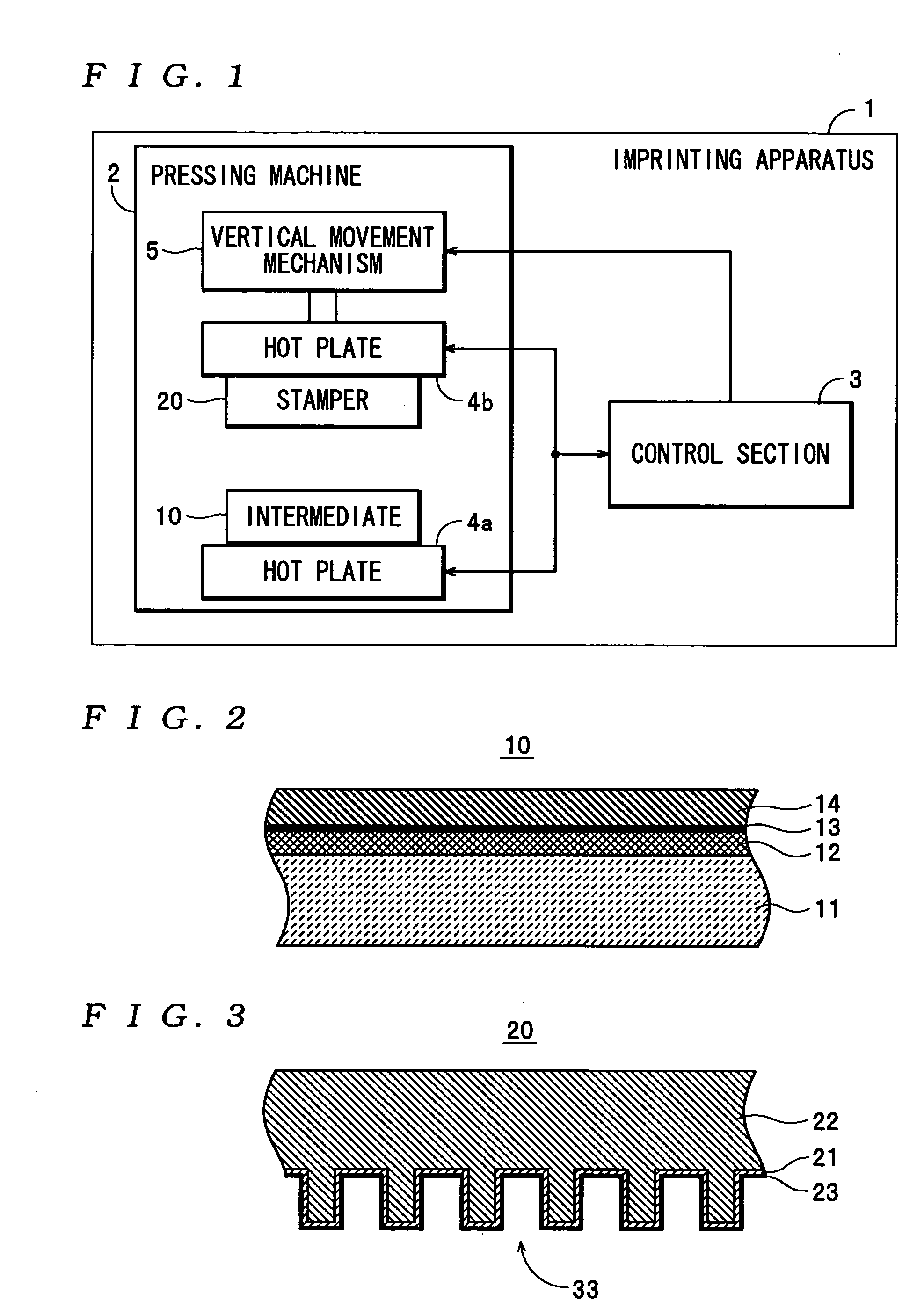
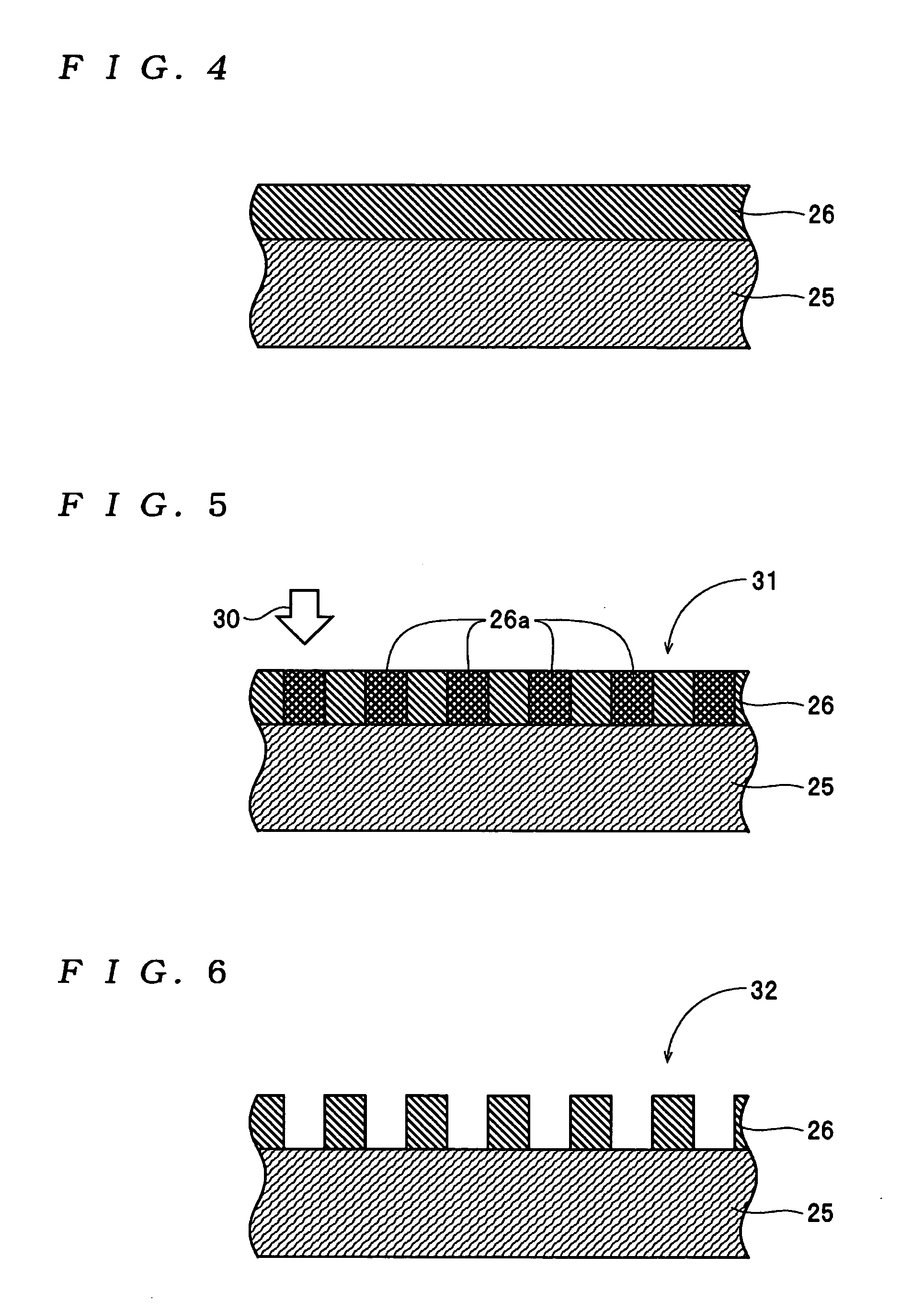
[0037] The imprinting apparatus 1 shown in FIG. 1 forms a concave / convex pattern 34 (see FIG. 12) by pressing a stamper 20 (see FIG. 3) against an intermediate 10 (see FIG. 2) by the imprinting method of the present invention, in manufacturing the information recording medium 40 shown in FIG. 13, and is comprised of a pressing machine 2, and a control section 3. In this embodiment, the information recording medium 40 is a discrete track-type magnetic recording medium, and formed with a concave / convex pattern 36 comprised of a large number of concentric data-recording tracks, servo patterns and the like separat...


PUM

PropertyMeasurementUnit
widthaaaaaaaaaa
thicknessaaaaaaaaaa
temperatureaaaaaaaaaa

Abstract

An imprinting method which is capable of forming a concave / convex pattern in a short time without causing deformation or incompleteness of the pattern. In the imprinting method, a stamper-pressing step of pressing a stamper against a resin layer formed by applying a resin material to a surface of a substrate, in a state of the resin layer being heated to a predetermined temperature, and a stamper-removing step of removing the stamper from the resin layer while maintaining either of the state of the resin layer being heated and a state of the temperature of the heated resin layer being held, are performed in the mentioned order, whereby shapes of recesses / protrusions of the stamper are transferred to the resin layer to form a concave / convex pattern on the substrate.

Description

BACKGROUND OF THE INVENTION [0001] 1. Field of the Invention [0002] The present invention relates to an imprinting method and an imprinting apparatus, for forming a concave / convex pattern on a substrate by pressing a stamper against a resin layer formed on a surface of the substrate to thereby transfer the concave / convex pattern, and an information recording medium-manufacturing method for manufacturing an information recording medium using the concave / convex pattern formed on the substrate. [0003] 2. Description of the Related Art [0004] Conventionally, photolithography has been known as a method of forming a fine concave / convex pattern (resist pattern) in a resist layer formed on a surface of a substrate, which is employed in processes for manufacturing semiconductor devices, information recording media, etc. The photolithography comprises irradiating the resist layer on the substrate with exposure light to form an exposure pattern in the resist layer, and then subjecting the resi...

Claims


Application Information

Patent Timeline
Patent Type & Authority Applications(United States)
IPC IPC(8): B29C43/02G11B5/84B29D17/00G03F7/00G11B5/855G11B7/26H01L21/027
CPCB29C43/003B29C43/021B29C43/52B29C2043/025G11B7/263B82Y10/00B82Y40/00G03F7/0002G11B5/855B29D17/00
Inventor FUJITA, MINORUHATTORI, KAZUHIROSOENO, YOSHIKAZUTAKAI, MITSURU
Owner TDK CORPARATION
Learn More