Burst frequency discrimination circuit

a frequency discrimination circuit and burst signal technology, applied in the field of burst signal discrimination circuits, can solve the problems of long grace of products, long time-consuming and laborious, and conventional broadcast system determination devices require a long time for determining, so as to achieve accurate extraction of burst signal portions, circuit scale can be reduced, and circuit scale can be further reduced

Inactive Publication Date: 2005-12-01
PANASONIC CORP
View PDF4 Cites 2 Cited by
  • Summary
  • Abstract
  • Description
  • Claims
  • Application Information

AI Technical Summary

Benefits of technology

[0024] As described above, a burst frequency discrimination circuit of the present invention uses the line synchronizing separation circuit, the burst gate pulse generation circuit and the burst extracting circuit to obtain a demodulated signal of a burst signal portion of the input signal, and the demodulated signal is compared with a predetermined value by the comparison circuit, the result of which is output as the burst frequency discrimination signal. Therefore, unlike in the prior art, it is not necessary to determine whether or not the clock is locked to the burst signal, and it is possible to instantaneously determine, based on the output burst frequency discrimination signal, whether the input signal is an NTSC signal or a PAL signal to appropriately change the settings of the product. Moreover, the bandpass filter circuit and the FM demodulation circuit can be used also as a portion of the circuit having the SECAM color demodulation function, whereby the circuit scale can be reduced.
[0025] Moreover, in the burst frequency discrimination circuit of the present invention, an operating clock of 17.7 MHz for processing a PAL signal or an operating clock of 14.3 MHz for processing an NTSC signal is selected based on clock switching signal. The picture signal processing circuit including the burst frequency discrimination circuit is operated by using the selected clock, and the burst gate pulse signal is generated by the burst gate pulse generation circuit using the horizontal synchronizing signal output from the line synchronizing separation circuit as a reference. Furthermore, the demodulated signal of the burst signal portion of the input picture signal is extracted by the burst extracting circuit, and the demodulated signal is compared with a predetermined value by the comparison circuit, the result of which is output as the burst frequency discrimination signal. Therefore, it is possible to instantaneously output a burst frequency discrimination signal without an erroneous determination even if noise is contained. Moreover, a single NTSC / PAL color-difference demodulation circuit can be commonly used for demodulating an NTSC color signal and a PAL color signal by switching the operating clock from one to another, whereby the circuit scale can be further reduced.
[0026] Particularly, according to the present invention, the burst gate pulse generation circuit generates the burst gate pulse signal using the rising edge signal of the horizontal synchronizing signal output from the rising-edge-detecting-type line synchronizing separation circuit as a reference, whereby it is possible to accurately extract the burst signal portion even if the operating clock is switched from one to another.
[0027] Moreover, with the burst frequency discrimination circuit of the present invention, the line synchronizing separation circuit and the burst gate pulse generation circuit are operated by using a fixed clock that is not switched from one to another by the clock switching signal, whereby the burst extracting circuit can accurately extract the burst signal portion even if the input picture signal is switched between an NTSC signal and a PAL signal. Then, the demodulated signal of the burst signal portion output from the burst extracting circuit is compared with a predetermined value by the comparison circuit, the result of which is output as the burst frequency discrimination signal. Therefore, it is possible to output a burst frequency discrimination signal with an even higher precision without an erroneous determination even if noise is contained.
[0028] In addition, in the burst frequency discrimination circuit of the present invention, the line synchronizing separation circuit detects the horizontal synchronizing signal from the input picture signal, and the pre-burst edge detection circuit outputs the pre-burst edge detection signal using the detected horizontal synchronizing signal as a reference, thus detecting the start position of the burst signal. The input picture signal is also demodulated by the FM demodulation circuit, and the trace-type burst gate pulse generation circuit generates the burst gate pulse signal starting from a start position of the burst signal portion that is determined as a position at which the demodulated signal becomes greater than a predetermined value during the period in which the pre-burst edge detection signal is high. Furthermore, the burst extracting circuit extracts the burst signal portion even more accurately from the demodulated signal output from the FM demodulation circuit, and the demodulated signal of the burst signal portion is compared with a predetermined value by the comparison circuit, the result of which is output as the burst frequency discrimination signal. Therefore, it is possible to instantaneously output a burst frequency discrimination signal with a high precision without an erroneous determination even if noise is contained and even if there is a shift in the position at which the burst signal is superimposed such as in a signal reproduced from a VCR.
[0029] Furthermore, the burst frequency discrimination circuit of the present invention includes, in addition to the bandpass filter circuit for separating a chroma signal from an input picture signal, the additional bandpass filter circuit for separating a broad-band chroma signal, wherein the normal bandpass filter circuit is selected when the operating clock is switched to 17.7 MHz by the clock switching signal, while the additional broad-band bandpass filter circuit is selected when the operating clock is 14.3 MHz, whereby a demodulation operation is performed by the FM demodulation circuit without attenuating the frequency component of the burst signal through the bandpass filter circuit section. Using the burst gate pulse signal output from the trace-type burst gate pulse generation circuit, the burst extracting circuit extracts the burst signal portion, and the demodulated signal of the burst signal portion is compared with a predetermined value by the comparison circuit, the result of which is output as the burst frequency discrimination signal. Therefore, it is possible to instantaneously determine the burst frequency and output a burst frequency discrimination signal with a high precision even if the input picture signal has a low amplitude or a shifted burst position.

Problems solved by technology

However, the conventional broadcast system determination device requires a long time for determining whether or not the APC circuit 111 is locked.
Although a blue screen or a black screen is displayed so that no video image is displayed during a period in which the broadcast system is being determined, i.e., during a period in which an abnormal signal is being output, such a period being long lowers the grace of the product.

Method used


Image

  • Burst frequency discrimination circuit
  • Burst frequency discrimination circuit
  • Burst frequency discrimination circuit

Examples


first embodiment

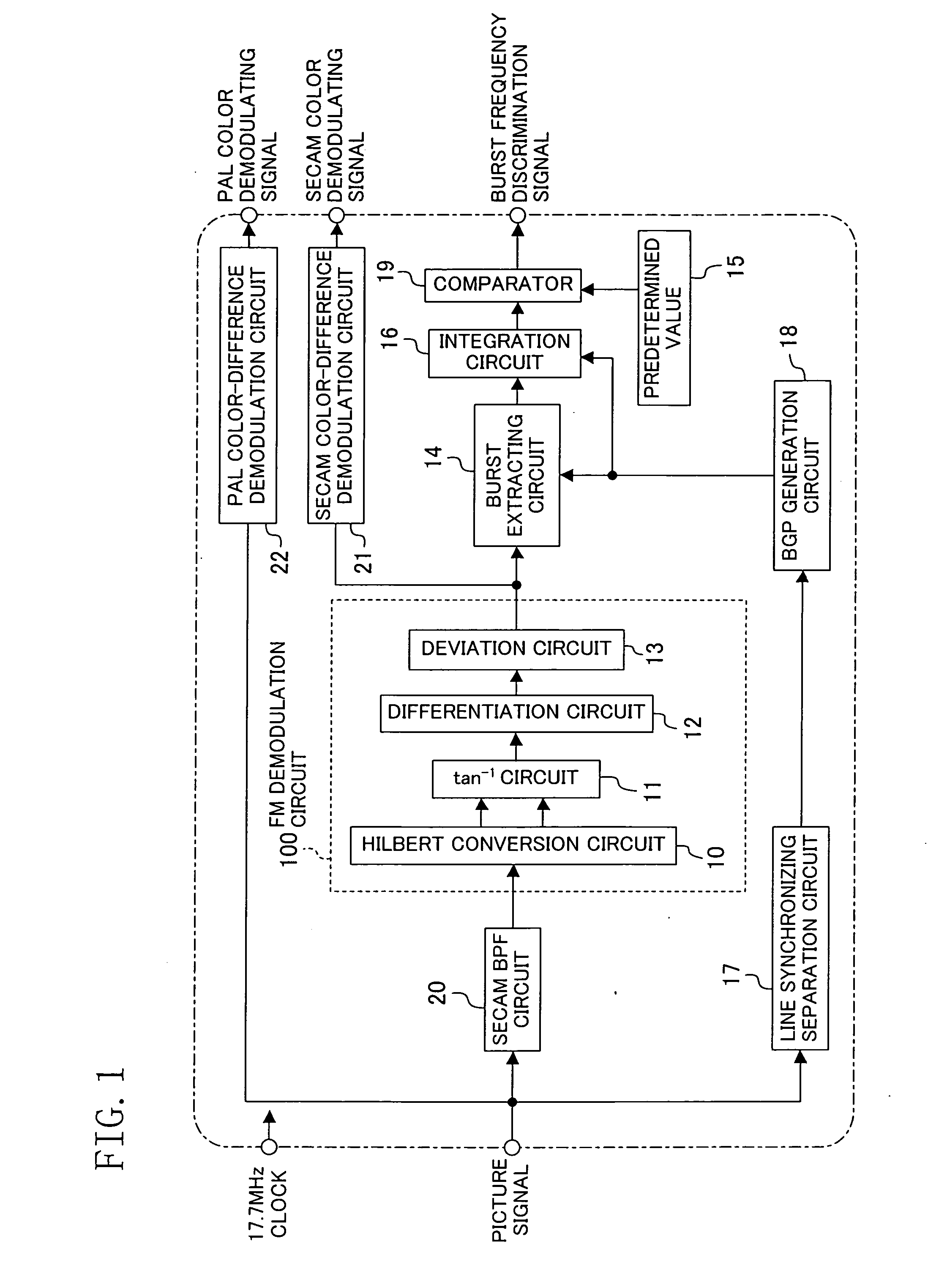
[0042]FIG. 1, FIG. 7A to FIG. 7D2 and FIG. 8A to FIG. 8G2 show a burst frequency discrimination circuit according to a first embodiment of the present invention.

[0043]FIG. 1 shows a configuration of a picture signal processing circuit including the burst frequency discrimination circuit of the present embodiment.

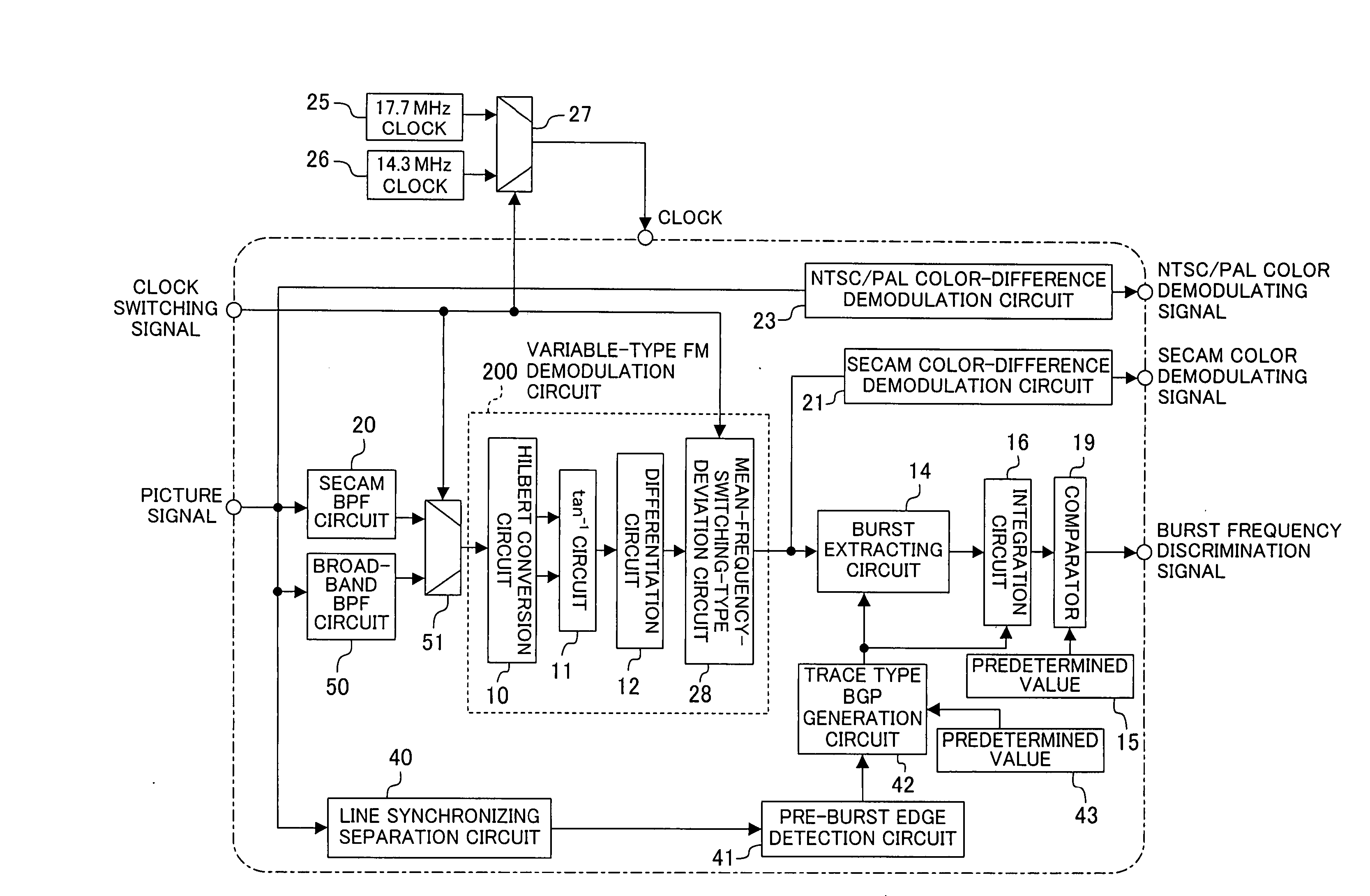
[0044] Referring to FIG. 1, the burst frequency discrimination circuit of the present embodiment includes a SECAM bandpass filter (SECAM BPF) circuit 20, a burst extracting circuit 14, an FM demodulation circuit 100, an integration circuit 16, a predetermined value 15, a comparator (comparison circuit) 19, a SECAM color-difference demodulation circuit 21, a PAL color-difference demodulation circuit 22, a line synchronizing separation circuit 17 and a BGP (burst gate pulse) generation circuit 18. The FM demodulation circuit 100 includes a Hilbert conversion circuit 10, an arc tangent circuit 11, a differentiation circuit 12 and a deviation circuit 13.

[0045] The configurati...

second embodiment

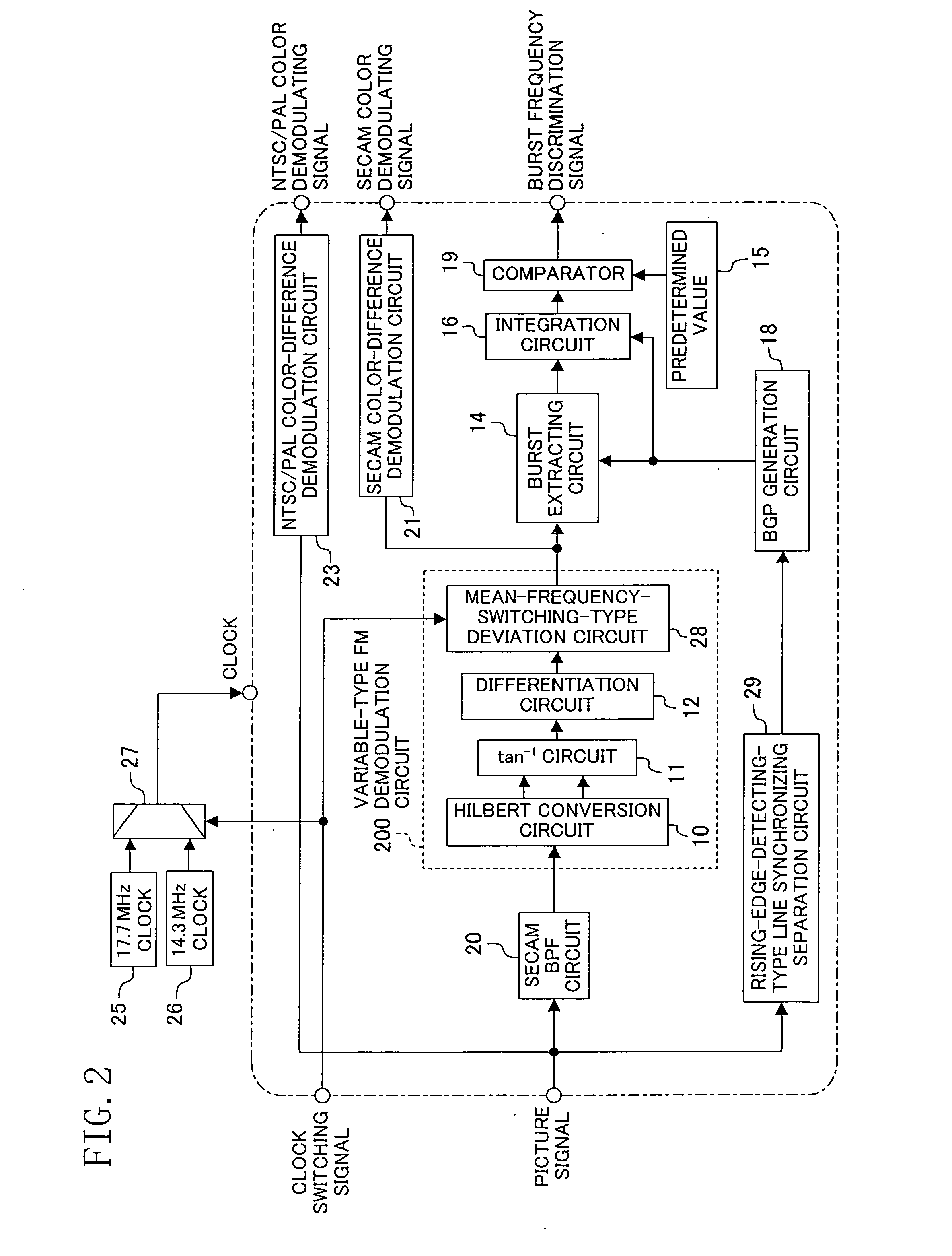
[0062] Next, a burst frequency discrimination circuit according to a second embodiment of the present invention will be described with reference to FIG. 2, FIG. 9A to FIG. 9D2 and FIG. 10A to FIG. 10D2.

[0063]FIG. 2 shows a configuration of a picture signal processing circuit including the burst frequency discrimination circuit of the present embodiment, and FIG. 9A to FIG. 9D2 and FIG. 10A to FIG. 10D2 show signal waveforms at different positions, where an NTSC signal or a PAL signal is input to the burst frequency discrimination circuit of the present embodiment.

[0064] Referring to FIG. 2, the burst frequency discrimination circuit of the present embodiment includes the SECAM BPF circuit 20, the burst extracting circuit 14, an FM demodulation circuit 200, the integration circuit 16, the predetermined value 15, the comparator 19, the SECAM color-difference demodulation circuit 21, an NTSC / PAL color-difference demodulation circuit 23, a rising-edge-detecting-type line synchronizing...

third embodiment

[0073] A burst frequency discrimination circuit according to a third embodiment of the present invention will now be described with reference to FIG. 3.

[0074]FIG. 3 shows a configuration of a picture signal processing circuit including the burst frequency discrimination circuit of the present embodiment. Referring to FIG. 3, the burst frequency discrimination circuit of the present embodiment includes a line synchronizing separation circuit 30 and a BGP generation circuit 31 operating at a fixed clock.

[0075] Other than this, the configuration is the same as that of the burst frequency discrimination circuit of the second embodiment. Therefore, like elements to those of the second embodiment will be denoted by like reference numerals, and will not be further described below.

[0076] In the line synchronizing separation circuit 30 for separating a horizontal synchronizing signal and generating the horizontal synchronizing signal as a reference signal, the falling edge of the horizont...


PUM


Abstract

A picture signal processing circuit capable of processing picture signals of various broadcast systems including the SECAM system, the PAL system and the NTSC system, wherein an FM demodulation circuit for demodulating a SECAM signal is used also as a portion of a burst frequency discrimination circuit. An input picture signal is demodulated by the FM demodulation circuit to obtain a frequency component thereof, and then a burst signal portion thereof is extracted by a burst extracting circuit. The extracted demodulated signal is integrated by an integration circuit, and compared with a predetermined value by a comparator, based on which the burst frequency is determined. Therefore, it is possible to instantaneously determine the burst frequency, and the circuit scale is reduced by sharing the FM demodulation circuit.

Description

CROSS REFERENCE TO RELATED APPLICATION [0001] This non-provisional application claims priority under 35 U.S.C. § 119(a) on Patent Application No. 2004-157073 filed in Japan on May 27, 2004, the entire contents of which are hereby incorporated by reference. BACKGROUND OF THE INVENTION [0002] The present invention relates to a burst frequency discrimination circuit for determining a broadcast system by determining the burst frequency of a broadcast signal for use in a picture signal process handling different types of broadcast signals such as NTSC signals and PAL signals, for example. [0003] There are various color television broadcast systems such as NTSC and PAL. For example, the color subcarrier frequency is 3.579545 MHz in the NTSC system and 4.43361875 MHz in the PAL system. There are some regions in Europe where signals of different broadcast systems can be received, and there are products such as TV sets and VCRs that are capable of handling color television broadcast signals ...

Claims


Application Information

Patent Timeline
Patent Type & Authority Applications(United States)
IPC IPC(8): H04N9/00H04N9/455H04N9/64H04N9/65
CPCH04N9/455
Inventor MURATA, HISAJIMIYOSHI, TOSHIHIRO
Owner PANASONIC CORP
Why Eureka
Try Eureka