Supercharge Your Innovation With Domain-Expert AI Agents!

Vertical light emitting type backlight module

a backlight module and light-emitting technology, applied in the field of vertical light-emitting type backlight modules, can solve the problems of light loss and complicated lenses, and achieve the effects of reducing light loss, simplifying lens structure, and reducing the change of path of ligh

Inactive Publication Date: 2005-12-01
SAMSUNG ELECTRONICS CO LTD
View PDF6 Cites 51 Cited by
  • Summary
  • Abstract
  • Description
  • Claims
  • Application Information

AI Technical Summary

Benefits of technology

The present invention provides a vertical light emitting type backlight module for a liquid crystal display that reduces light loss by minimizing the change of light path. The module comprises LED array modules and a reflection plate for redirecting the light emitted from the LED devices in a perpendicular direction. The LED devices are mounted on a substrate and surrounded by lenses for directing the light in a specific angle. The LED array modules are supported by a support to ensure proper positioning. The LED devices may comprise white LED chips or a combination of red, blue, and green LED chips. The support may be made of a metallic material with high thermal conductivity. The LED devices may also have a reflection plate with a wide reflection angle in a parallel direction and a narrow reflection angle in a perpendicular direction. The reflection plate may have an elliptical shape with a major diameter parallel to the plane of the backlight module and a minor diameter perpendicular to the plane of the backlight module. The technical effects of the invention include reduced light loss, simplified lens structure, easy manufacturing and design, and improved lighting efficiency.

Problems solved by technology

Although the lens has a mortar-like shape in FIG. 1, there are problems in that, according to the emitting angle of the light generated from the LED chip 14, the lens may be more complicated, and in that the light deviated from ranges corresponding to an optical design thereof can be directed in the vertical direction without being refracted in the horizontal direction.
As described above, with the backlight module 30 employing the conventional LED, the light initially generated by the LED chip 14 practically used as the light source is refracted in the horizontal direction by the lens 13, and is then reflected in the vertical direction by the reflection plate 31, whereby the path of the light is changed several times. As a result, there are several problems in that, firstly, the lens has a complicated structure in order to reflect the light generated by the LED chip 14 in the horizontal direction, thereby complicating the design and the manufacturing, in that, secondly, while initially generated light is forced to follow the path of the light changed several times, light loss can occur, in that, thirdly, when the light is refracted using the differences in refraction rates, since the light generated from the center of the LED device in a direction of an upper portion of the LED device is transmitted without having its direction changed, there can occur a hot spot at the center of the LED device, thereby requiring a shadow sheet for the backlight module 30 in order to prevent the hot spot from being generated.

Method used


Image

  • Vertical light emitting type backlight module
  • Vertical light emitting type backlight module
  • Vertical light emitting type backlight module

Examples


Embodiment Construction

[0031] Now preferred embodiments of the present invention will be described in detail with reference to the accompanying drawings so that those skilled in the art may easily understand and repeat the present invention.

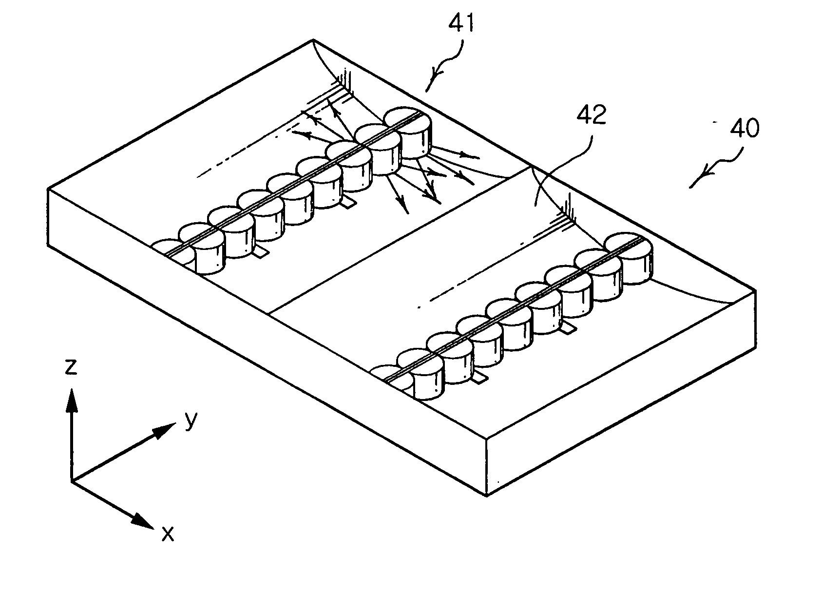
[0032]FIG. 4 is a perspective view showing a vertical light emitting type backlight module according to an embodiment of the present invention.

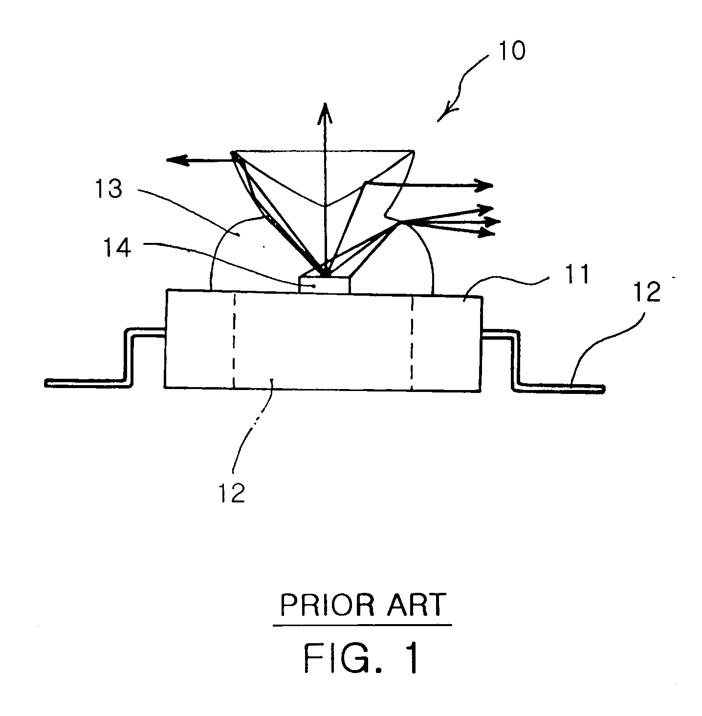
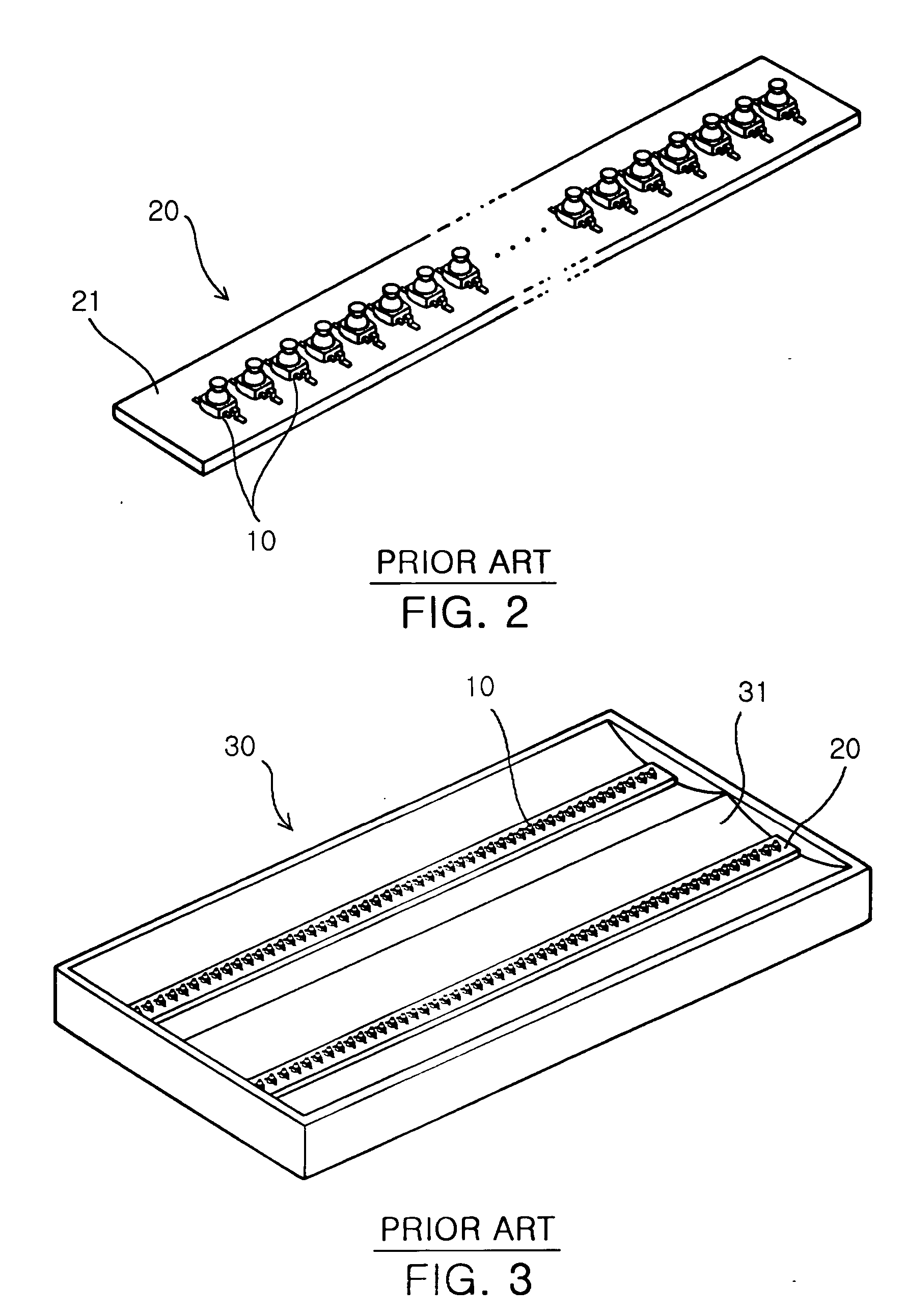
[0033] Referring to FIG. 4, a vertical light emitting type backlight module 40 comprises one or more LED array modules 41, in which a plurality of LED chips are arranged in a line such that light generated from the LED chips is emitted in the horizontal direction, and a reflection plate 42 for reflecting the light emitted in the horizontal direction from the LED array module 41. The schematic shape of the vertical light emitting type backlight module 40 according to the present invention is similar to that of the conventional backlight module shown in FIG. 3.

[0034] However, according to the present invention, the LED array mo...


PUM

PropertyMeasurementUnit
conductiveaaaaaaaaaa
angleaaaaaaaaaa
heightaaaaaaaaaa

Abstract

Disclosed herein is a vertical light emitting type backlight module, for irradiating white light to the rear side of a liquid crystal display in the perpendicular direction. The vertical light emitting type backlight module comprises a) one or more LED array modules, each comprising a substrate having conductive patterns printed on upper and lower surfaces of the substrate, respectively, a plurality of LED devices mounted on the upper and lower surfaces of the substrate, respectively, for emitting light toward the front of respective surfaces of the substrate with the LED devices mounted thereon, and a plurality of lenses formed to surround the LED devices, respectively, for directing the light emitted from the LED devices in a direction perpendicular to the LED while being within a predetermined angle from an axis parallel to a plane of the backlight module, the substrate being mounted perpendicular to the plane of the backlight module such that the light emitted from the LED devices is emitted in a direction approximately parallel to the plane of the backlight module, and b) a reflection plate for each of the LED array modules for reflecting the light spread in the horizontal direction to change path of the light to the perpendicular direction.

Description

BACKGROUND OF THE INVENTION [0001] 1. Field of the Invention [0002] The present invention relates to a vertical light emitting type backlight module, which provides an image by directly emitting light from the underneath of an LED (Light Emitting Diode) panel, and more particularly to a vertical light emitting type backlight module of a liquid crystal display, which has reduced change of path of light, thereby decreasing light loss, while having a simplified lens structure, thereby allowing easy manufacturing and design. [0003] 2. Description of the Related Art [0004] As a current developing trend in the electronic equipment industry, LCDs (Liquid Crystal Display) have been spotlighted as next generation display devices. However, since LCDs do not emit light on their own, an LCD panel for communication is provided, at the rear side thereof, with a backlight for emitting light. [0005] The backlight enables colors of an image realized by the LCD panel to be reproduced nearly into real...

Claims


Application Information

Patent Timeline
Patent Type & Authority Applications(United States)
IPC IPC(8): F21K99/00F21V7/04G02F1/13357
CPCG02F1/133603F21K9/00F21Y2105/10F21Y2115/10G02F1/1335
Inventor KIM, HYUNG SUKPARK, YOUNG SAMHAHM, HUN JOOPARK, JUNG KYUJEONG, YOUNG JUNE
Owner SAMSUNG ELECTRONICS CO LTD
Features
  • R&D
  • Intellectual Property
  • Life Sciences
  • Materials
  • Tech Scout
  • Unparalleled Data Quality
  • Higher Quality Content
  • 60% Fewer Hallucinations
Learn More