Spacerless artificial disc replacements

a technology of artificial discs and spacers, applied in the field of artificial disc replacements, can solve problems such as design complexity, and achieve the effect of facilitating more normal spinal flexion, extension, and lateral bending

Inactive Publication Date: 2005-12-01
HOWMEDICA OSTEONICS CORP
View PDF98 Cites 30 Cited by
  • Summary
  • Abstract
  • Description
  • Claims
  • Application Information

AI Technical Summary

Benefits of technology

[0007] The present invention replaces polyethylene artificial disc replacement (ADR) spacers with harder, more wear resistant materials. In the preferred embodiments, an ADR according to the invention includes opposing saddle-shaped components to facilitate more normal spinal flexion, extension, and late...

Problems solved by technology

Instead, axial rotation is limited through the use of multiple ball-and-so...

Method used


Image

  • Spacerless artificial disc replacements
  • Spacerless artificial disc replacements
  • Spacerless artificial disc replacements

Examples


Embodiment Construction

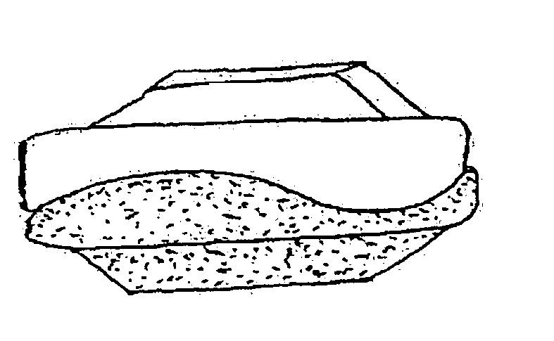
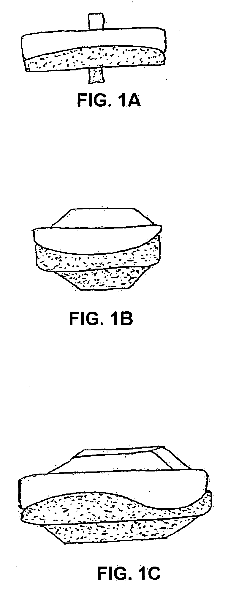
[0022]FIG. 1A is an anterior view of an ADR according to the invention. FIG. 1B is a lateral view of the ADR of FIG. 1. FIG. 1C is an oblique view of the ADR of FIG. 1.

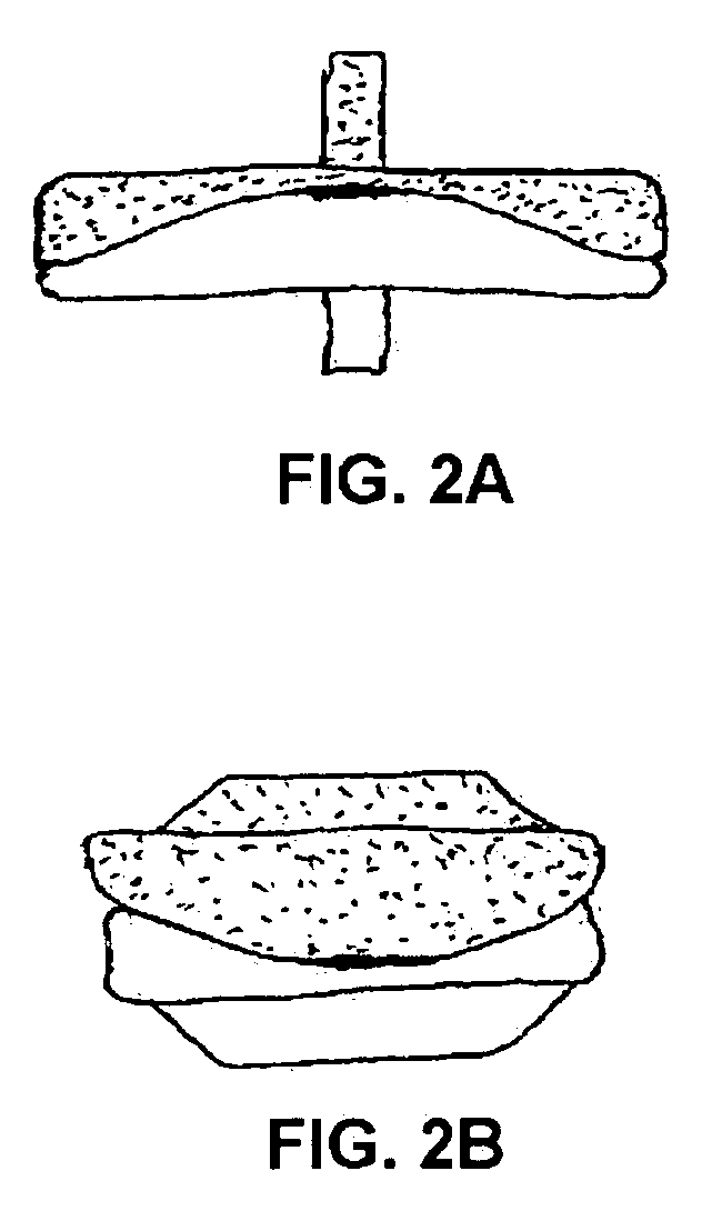
[0023]FIG. 2A is a view of the anterior aspect of an alternative embodiment of the ADR, wherein the articulating surfaces of both components have a flat area centrally from the front to the back of the ADR. FIG. 2B is a view of the lateral aspect of an alternative embodiment of the ADR drawn in FIG. 2B. The flat area of the articulating surfaces courses centrally from side of the DR to the other side. The flat area allows one component to translate slightly on the other component. Alternatively, a curved area with a large radius could replace the flat area.

[0024]FIG. 3A is a view of the anterior aspect of an alternative, less constrained, embodiment of the saddle-shaped ADR drawn in a fully flexed position. The less constrained embodiment facilitates spinal flexion, extension, and lateral bending. FIG. 3B is a view ...


PUM


Abstract

Spacerless artificial disc replacements (ADR) are disclosed. One preferred embodiment includes two saddle-shaped components to facilitate more normal spinal flexion, extension, and lateral bending while limit axial rotation, thereby protecting the facet joints and the annulus fibrosus (AF). Either or both of the superior and inferior components are made of a hard material such as chrome cobalt, titanium, or a ceramic including alumina, zirconia, or calcium phosphate. The articulating surfaces of the ADR are also preferably highly polished to reduce friction between the components. Metals, alloys or other materials with shape-memory characteristics may also prove beneficial.

Description

REFERENCE TO RELATED APPLICATION [0001] This application claims the benefit of the filing date of U.S. Provisional Patent Application No. 60 / 372,520, filed Apr. 12, 2002 and this application is a continuation of U.S. application Ser. No. 10 / 413,028, filed on Apr. 14, 2003, the disclosures of which are incorporated herein by reference.FIELD OF THE INVENTION [0002] This invention relates generally to artificial disc replacements (ADRs) and, more particularly, to devices that operate without softer spacer materials such as polyethylene. BACKGROUND OF THE INVENTION [0003] Polyethylene spacers are common in some artificial joint situations, including total knee replacements (TKRs). Polyethylene spacers are also used between metal plates in many artificial disc replacement (ADR) designs. [0004] Complications arising from poly debris are well documented, however, including fracture of the spacer once it becomes too thin, absorptions and migration of poly particles throughout the body, and ...

Claims


Application Information

Patent Timeline
IPC IPC(8): A61F2/00A61F2/30A61F2/44A61F2/46A61L27/04
CPCA61F2/30767A61L2430/38A61F2002/30092A61F2002/30301A61F2002/30528A61F2002/30878A61F2002/30884A61F2002/30934A61F2002/4631A61F2210/0014A61F2220/0025A61F2230/0095A61F2310/00023A61F2310/00029A61F2310/00203A61F2310/00239A61F2310/00293A61L27/04A61L27/10A61F2/4425A61F2310/00011A61F2/442A61F2002/302
Inventor FERREE, BRET A.TOMPKINS, DAVID
Owner HOWMEDICA OSTEONICS CORP
Why Eureka
Try Eureka