

Systems and methods to determine elastic properties of materials
a nonlinear elastic and material technology, applied in the direction of analyzing solids using sonic/ultrasonic/infrasonic waves, analyzing material hardness using single impulsive force, etc., can solve the problem of difficult to reliably determine elastic properties, time-consuming, costly or impractical to constrain the material in a test apparatus, and limit the usefulness of these methods to low-amplitude driving forces
Inactive Publication Date: 2005-12-01
GERMAN PETER THOMAS
View PDF2 Cites 112 Cited by
- Summary
- Abstract
- Description
- Claims
- Application Information
AI Technical Summary
Benefits of technology
[0248] Therefore, another method for resolving the mass-stiffness ambiguity comprises analyzing the anharmonic driving-point motions typical of real nonlinear materials. If the amplitude and phase relationships of the harmonic components are substantially preserved, then the anharmonic driving-point motions may be analyzed to unambiguously determine the three independent parameter coefficients in equation (11). It is an advantage of the present invention that elastic properties can be determined by analyzing a driving-point response comprising an anharmonic response.
[0249] Another method for resolving the inherent ambiguity in the mass m and stiffness k1 in the linear model is by a combination solution method using two or more distinct differential equation models, which I describe elsewhere in this application.
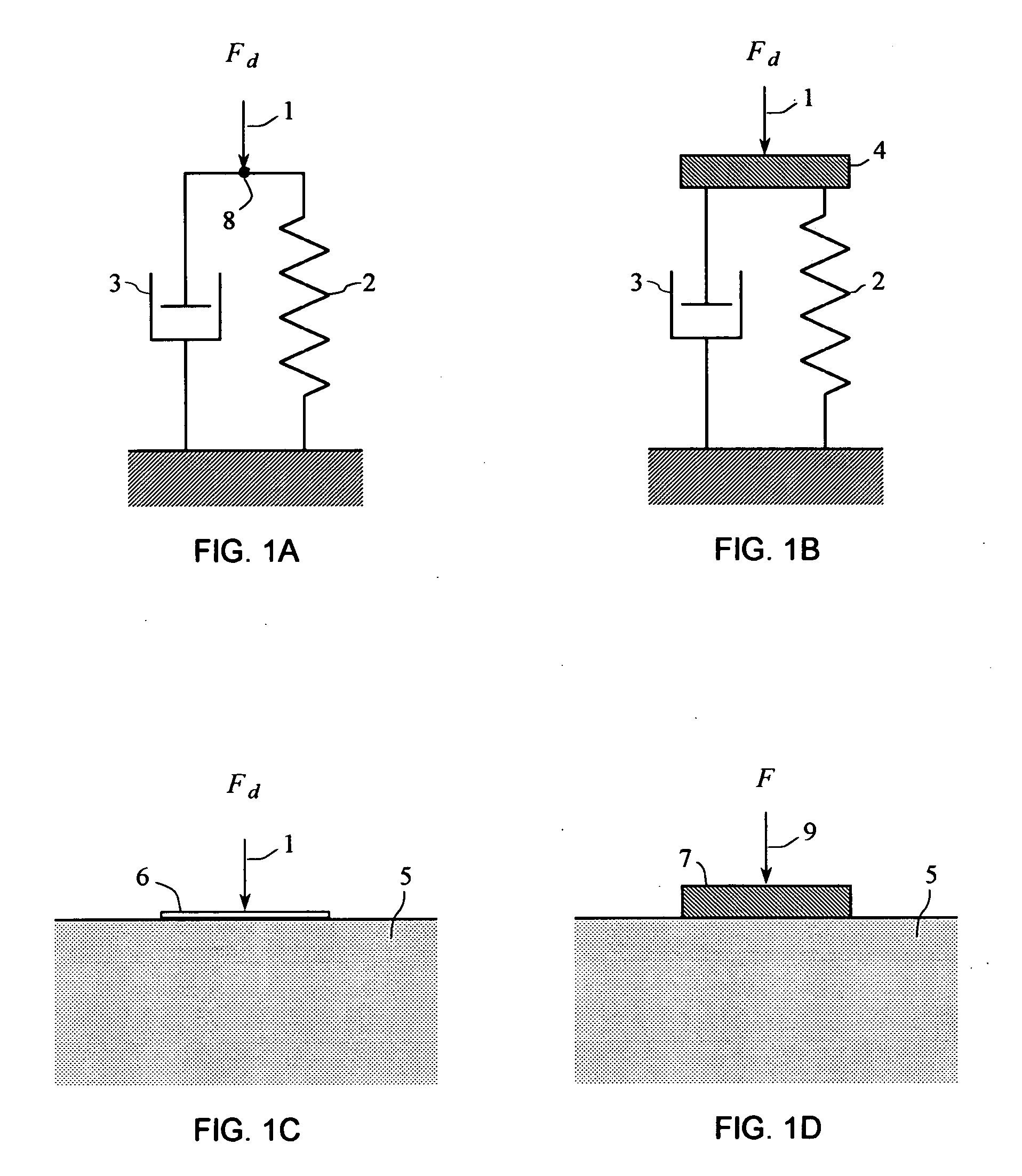
[0250] If the acceleration and mass of the mass element 4 are known quantities, then a massless model can be formed by moving the inertial force component to the right-hand side of the differential equations (10) and (11), thereby forming a driving force comprising the combination of the inertial force and the force 1 acting on the mass element 4. For example, if the acceleration and mass of the mass element 4 in FIG. 1B are known, then the inertial force component can be subtracted from the driving force 1 to produce a force representative of a driving force acting on a massless system.
[0251]FIG. 1A depicts a massless model comprising a spring-damper system, wherein the driving force Fd acts on a spring element 2 and a damper element 3. The spring element 2 and the damper element 3 are assumed to be massless. In this model, the driving force Fd acts on the spring element 2 and damper element 3 at a point 8, and the motion of the point 8 represents the driving-point motion of the elastic material. The elastic force exerted by the spring element 2 and the viscous force exerted by the damper element 3 are equivalent to the corresponding forces and elements described for FIG. 1B.
[0252] A force balance differential equation model for a nonlinear spring-damper system comprises equating the driving force to the sum of a nonlinear elastic force and a nonlinear viscous force. The force balance differential equation model of a nonlinear spring-damper system can be expressed mathematically as follows: ∑i=1Lbivi+∑i=1nkixi=Fd(14) where Fd represents the driving force, the first summation represents the viscous force, and the second summation represents the elastic force. Equation (14) is a representation of a general differential equation model of a nonlinear spring-damper system.
[0253] Similarly, a force balance differential equation model for a linear spring-damper system comprises equating the driving force to the sum of a linear elastic force and a linear viscous force. The force balance differential equation model of a linear spring-damper system comprises the linear terms of equation (14): b1v+k1x=Fd. (15)
Problems solved by technology
However, for many important types of materials it is time consuming, costly, or impractical to constrain the material in a test apparatus.
However, it is a difficult problem to reliably determine elastic properties from the unconstrained driving-point motions of a real material.
These assumptions limit the usefulness of these methods to low-amplitude driving forces applied for sufficiently long duration to approximate a steady-state response.
The low-amplitude limitation also restricts the usefulness in fields where larger driving-forces might otherwise be advantageous.
For example, seismic vibrators used in seismic surveying produce very large driving forces far in excess of the low-amplitude limitations of the existing analysis methods.
The problem is that the stiffness and viscosity of a real, unconstrained material are a complicated function of frequency, and may not be well represented by an average value over a wide range of frequencies.
Furthermore, the transient and anharmonic response components represent useful information about the elastic properties of real, nonlinear elastic material, so attenuating these components causes a loss of useful information.
The transient components and anharmonic frequency components can represent a substantial portion of the total elastic energy in the measured motion of the driving point motion, and attenuating these components results in a misrepresentation of the relationship of the driving-force to the motion.
Therefore, existing practices for analyzing a measured driving-point response to determine elastic properties of a material are of questionable reliability and subject to a number of substantial limitations.
If the deforming forces are sufficiently large, the material may not completely recover and may remain deformed after the external forces are removed.
Most real materials are not perfectly elastic.
The delay in the elastic response is also characterized by dissipation of the energy of the dynamic deforming forces, and it produces a damping effect on free vibrations of the material by dissipating the elastic energy.
For a semi-infinite body of material, the radiation of elastic-waves represents a significant loss of energy and a significant damping effect on the elastic response.
However, the transient response and the anharmonic response represent useful information about the elastic properties of real, nonlinear elastic material, so attenuating these components causes a loss of useful information.
The transient components and anharmonic frequency components can represent a substantial portion of the total elastic energy in the driving-point response, and attenuating these components results in a misrepresentation of the relationship of the driving-force to the response.
Method used
View moreImage
Smart ImageViewing Examples

Examples
example 1
[0644] Elastic properties of the soil at the surface of the earth at a test location were determined from the driving-point response of the soil, using an embodiment of the systems and methods of the present invention. A seismic vibrator actuator generated the driving force applied to the soil, and a vibrator control system acquired signals representative of the driving-point response of the soil. The soil being tested was in situ, in place at the surface of the earth.
Login to View More PUM
| Property | Measurement | Unit |
|---|---|---|
| frequency | aaaaa | aaaaa |
| ending frequency f2 | aaaaa | aaaaa |
| ending frequency f2 | aaaaa | aaaaa |
Abstract
The present invention provides systems and methods to use a measured driving-point response of a nonlinear material to determine one or more elastic properties of the material. The present invention takes advantage of the full information represented by the transient component, the steady-state component, the anharmonic components, and the nonlinear response components of a measured driving-point response of a real nonlinear material, without limitation in the use of large-amplitude forces. The elastic properties are determined by forming and solving a time-domain system of linear equations representing a differential equation model of the driving-point motions of the material. Based on a single, short duration, large-amplitude driving point measurement, both linear and nonlinear properties can be determined; both large-amplitude and near-zero amplitude properties can be determined; and elastic-wave speed and elastic moduli and their variation with depth can be determined. The present invention also provides a system and a method to filter an input signal to either attenuate or preserve each of one or more selected harmonic components that are harmonics of a phase reference signal.
Description
[0001] This application claims the priority of U.S. Provisional Patent Application Ser. No. 60 / 557,365, filed Mar. 29, 2004, the contents of which are hereby incorporated by reference in their entirety. [0002] Throughout this application various publications are referenced. The disclosures of these publications in their entireties are hereby incorporated by reference into this application in order to more fully describe the state of the art to which this invention pertains.FIELD OF THE INVENTION [0003] The present invention relates to the measurement of properties of nonlinear elastic materials, and more particularly to systems and methods for measurement of elastic properties based on a driving-point response of a nonlinear elastic material; to systems of linear equations; and to signal filtering. In one embodiment the present invention relates to measurement of in situ elastic properties of earth materials, such as foundation soils or geologic formations. In another embodiment the...
Claims
Login to View More Application Information
Patent Timeline
 Patent Type & AuthorityApplications(United States)
IPC IPC(8): G01N3/00G01N3/02G01N3/30G01N3/48G01V1/30H03H17/02
CPCG01N3/30G01N3/48G01N2203/0051H03H17/025G01N2203/0218G01N2291/02827G01N2203/0075
InventorGERMAN, PETER THOMAS
OwnerGERMAN PETER THOMAS