

Brake rotor
a brake rotor and rotor technology, applied in the direction of brake discs, brake drums, braking systems, etc., can solve the problems of rotor warping, unbalanced heat load on the disc brake rotor assembly, and limited airflow, so as to increase the brake performance and reduce the cooling efficiency of the disc brake rotor
- Summary
- Abstract
- Description
- Claims
- Application Information
AI Technical Summary
Benefits of technology
Problems solved by technology
Method used
Image

Examples
Embodiment Construction
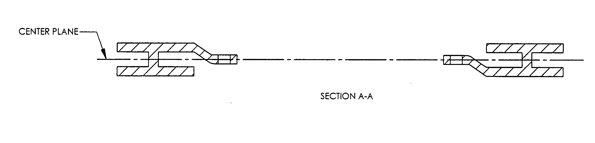
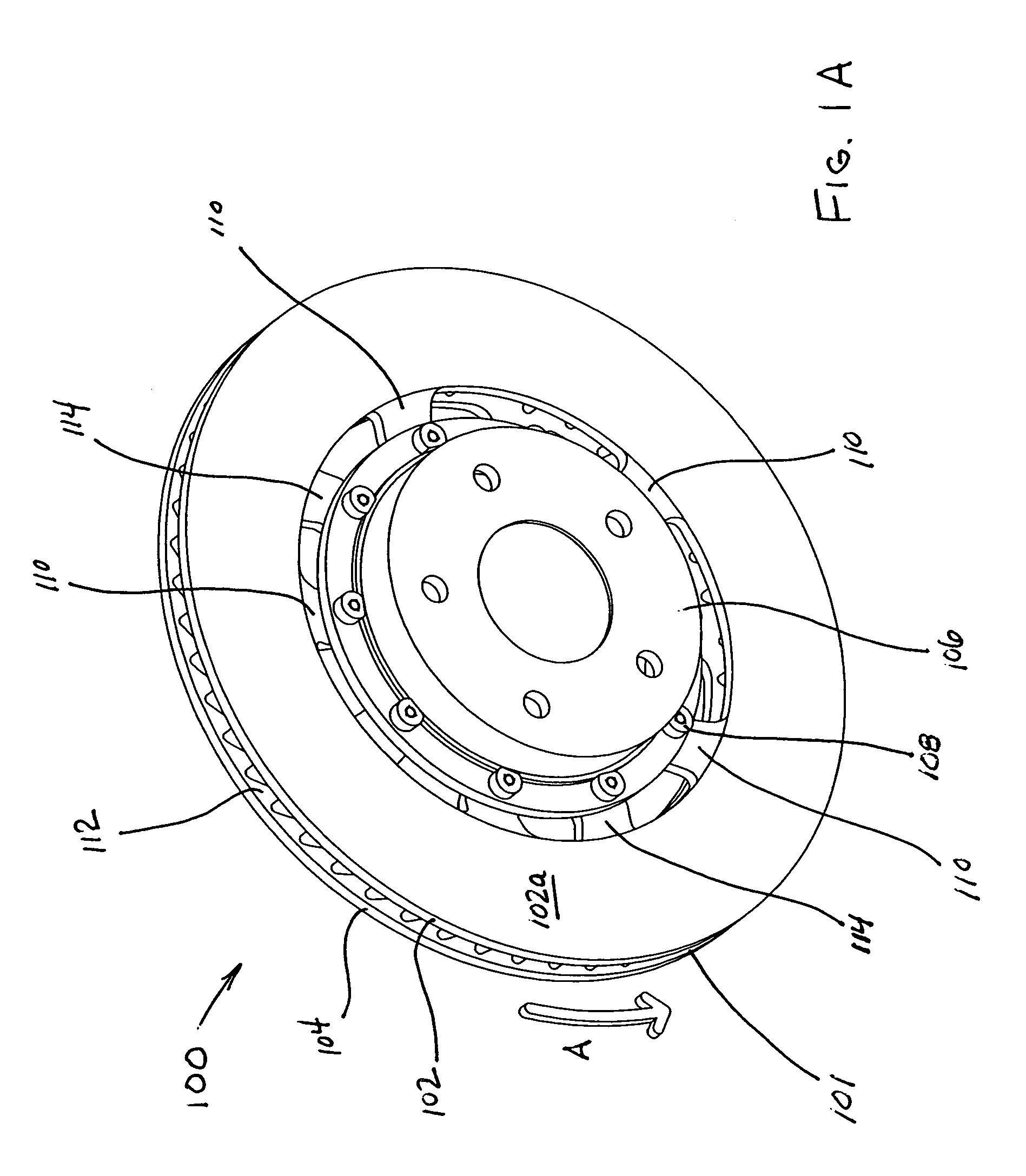
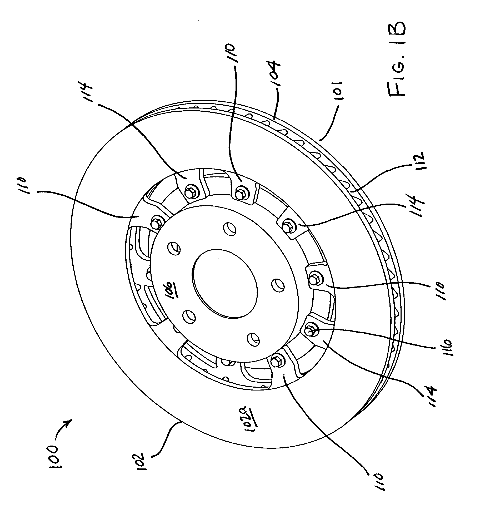
[0022] As shown in FIGS. 1-5, a disc brake rotor assembly 100, for example, may include a rotor ring 101 and a rotor hat 106. The rotor ring may include a first side 102 having a annular braking surface 102a . Such a surface may include other features, including slots and openings for venting gasses and materials produced as a result of a braking pad coming into contact with the surface during use (see, for example, co-pending U.S. patent application Ser. No. 10 / 608,246, filed Jun. 27, 2003, the entire disclosure of which is herein incorporated by reference).
[0023] As shown in the figures, the rotor hat may be mounted from the “top”—e.g., the side of the rotor ring having annular braking surface 102a (see FIGS. 1A and 2A), or from the “bottom”—e.g., the of the rotor ring having annular braking surface 104a (see FIGS. 1B and 2B).
[0024] The first side 102 may also include a plurality of mounting portions 110 (e.g., flanges), each having an opening 110a, for receiving a fastener 108 / ...
PUM
 Abstract
Description
Claims
Application Information