Method and system for monitoring module power status in a communication device

a communication device and power status technology, applied in power management, instruments, high-level techniques, etc., can solve problems such as “spots” over the module, liquid crystal just above the module may begin to boil and form bubbles, and certain modules within the chip may utilize excessive power

Inactive Publication Date: 2005-12-08
AVAGO TECH WIRELESS IP SINGAPORE PTE
View PDF7 Cites 25 Cited by
  • Summary
  • Abstract
  • Description
  • Claims
  • Application Information

AI Technical Summary

Benefits of technology

[0012] These and other advantages, aspects and novel features of the present invention, as well as details of

Problems solved by technology

Certain modules within the chip may utilize excessive power due to, for example, being turned on for a prolonged period of time.
Due to the continuous or increased power consumption in such module, the liquid crystal just above the module may begin to boil and form bubbles.
The boiling of the liquid crystal above the module may lead to discoloration and the appearance of “spots” over the module with excessive power consumption.
While this conventional method

Method used


Image

  • Method and system for monitoring module power status in a communication device
  • Method and system for monitoring module power status in a communication device
  • Method and system for monitoring module power status in a communication device

Examples


Embodiment Construction

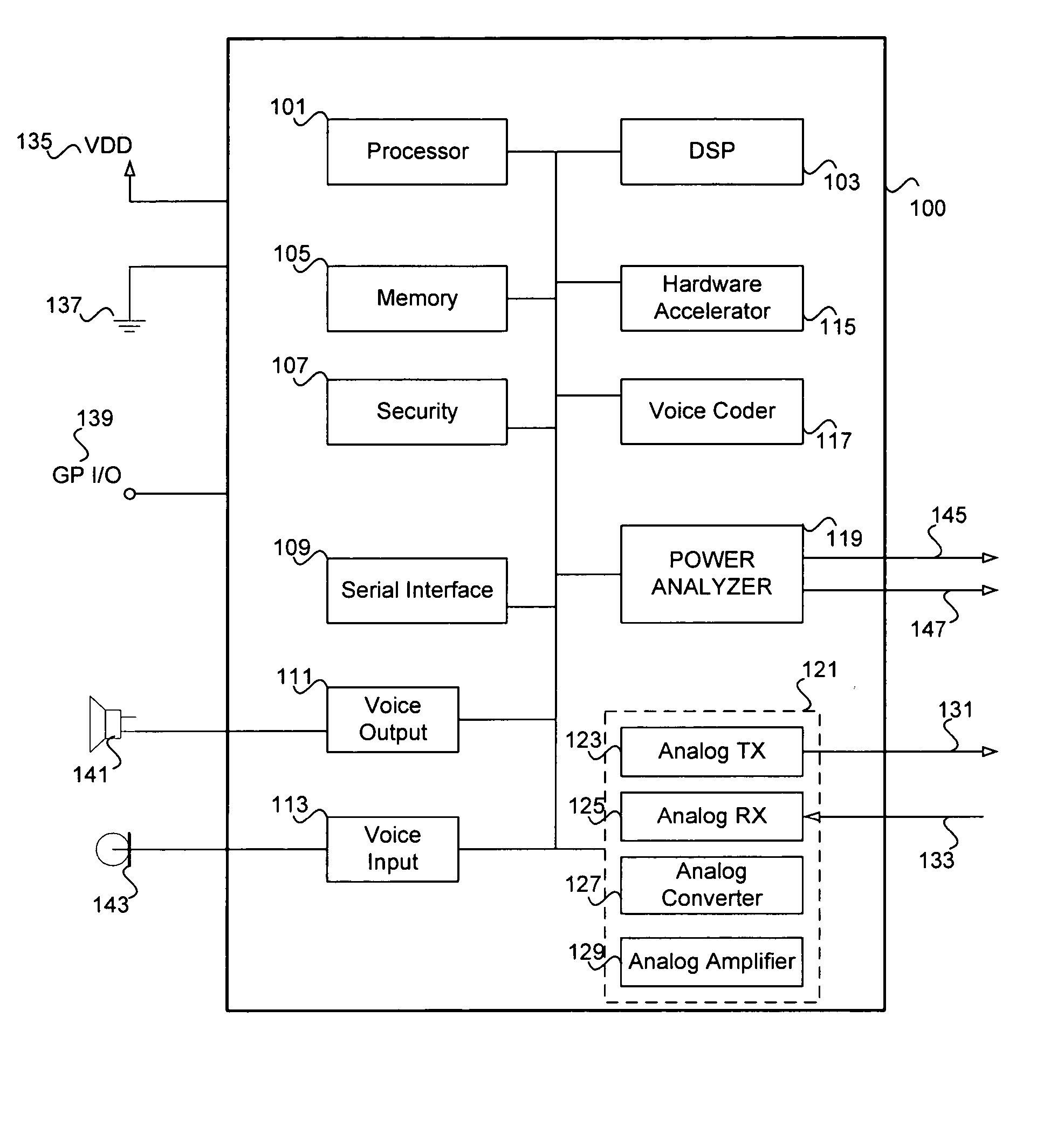
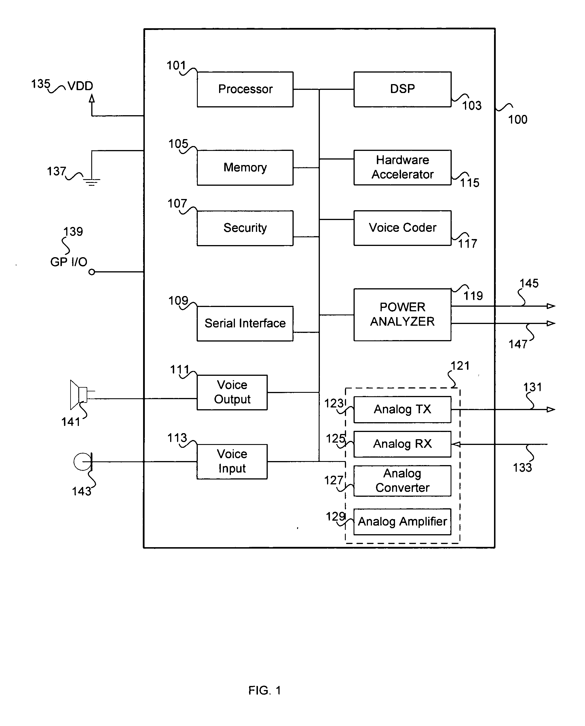
[0019] Certain aspects of the invention may be found in a method and system for monitoring operating status of a device, such as a wireless handset for example. A signal indicative of a power status of an on-chip device may be received by a power analyzer module within a chip. An output signal indicative of the received power status may be generated within the chip, while the chip is operating. The signal indicative of the power status may be communicated outside the chip via a serial bus, via separate output pins, and / or via general purpose input / output pins. The power status signal may then be processed by an external processing system such as a PC. The PC may display a list, for example, of the devices within the chip that utilize the most power. Other processing may be applied once the signal indicative of power status is communicated outside the chip.

[0020]FIG. 1 is a block diagram of an exemplary chip architecture that may be utilized in accordance with an embodiment of the i...


PUM


Abstract

Methods and systems for monitoring operating status of a device are provided. Aspects of the method may include receiving within a chip, a signal indicative of a power status of an on-chip device. An output signal indicative of the power status may be generated from within the chip, while the chip is operating. The generated output signal may be communicated outside the chip via a serial bus, a plurality of pin connections on said chip, and/or a general purpose input/output connection. The generated output signal may be multiplexed on at least one pin on the chip and it may comprise a clock signal and/or a data signal. The data signal may comprise sequential power status information for a plurality of on-chip devices.

Description

CROSS-REFERENCE TO RELATED APPLICATIONS / INCORPORATION BY REFERENCE [0001] This application makes reference to, claims priority to, and claims the benefit of U.S. Provisional Application Ser. No. 60 / 577,263 (Attorney Docket No. 15615US01) filed Jun. 4, 2004 and entitled “Method And System For Monitoring Module Power Status In A Communication Device.”[0002] The above stated application is hereby incorporated herein by reference in its entirety.FIELD OF THE INVENTION [0003] Certain embodiments of the invention relate to monitoring operating status of a communication device. More specifically, certain embodiments of the invention relate to a method and system for monitoring power status of various modules in a communication device such as a wireless handset. BACKGROUND OF THE INVENTION [0004] Power usage is an important factor in wireless communications, especially for mobile communication devices that have a very limited battery capacity. With on-going development of wireless technolog...

Claims


Application Information

Patent Timeline
IPC IPC(8): G01R31/02G01R31/28G01R31/317H04M1/73
CPCH04W52/0251G01R31/31721Y02D30/70
Inventor CHASE, BRYAN
Owner AVAGO TECH WIRELESS IP SINGAPORE PTE
Why Eureka
Try Eureka