

Positioning system with intentional multi-path signal
a multi-path signal and positioning system technology, applied in the field of positioning systems, can solve the problems of low accuracy, laser systems currently employ expensive pointing mechanisms, and acoustic systems can only measure the range to accuracies of a centimeter or more, and achieve the effect of high accuracy
- Summary
- Abstract
- Description
- Claims
- Application Information
AI Technical Summary
Benefits of technology
Problems solved by technology
Method used
Image

Examples
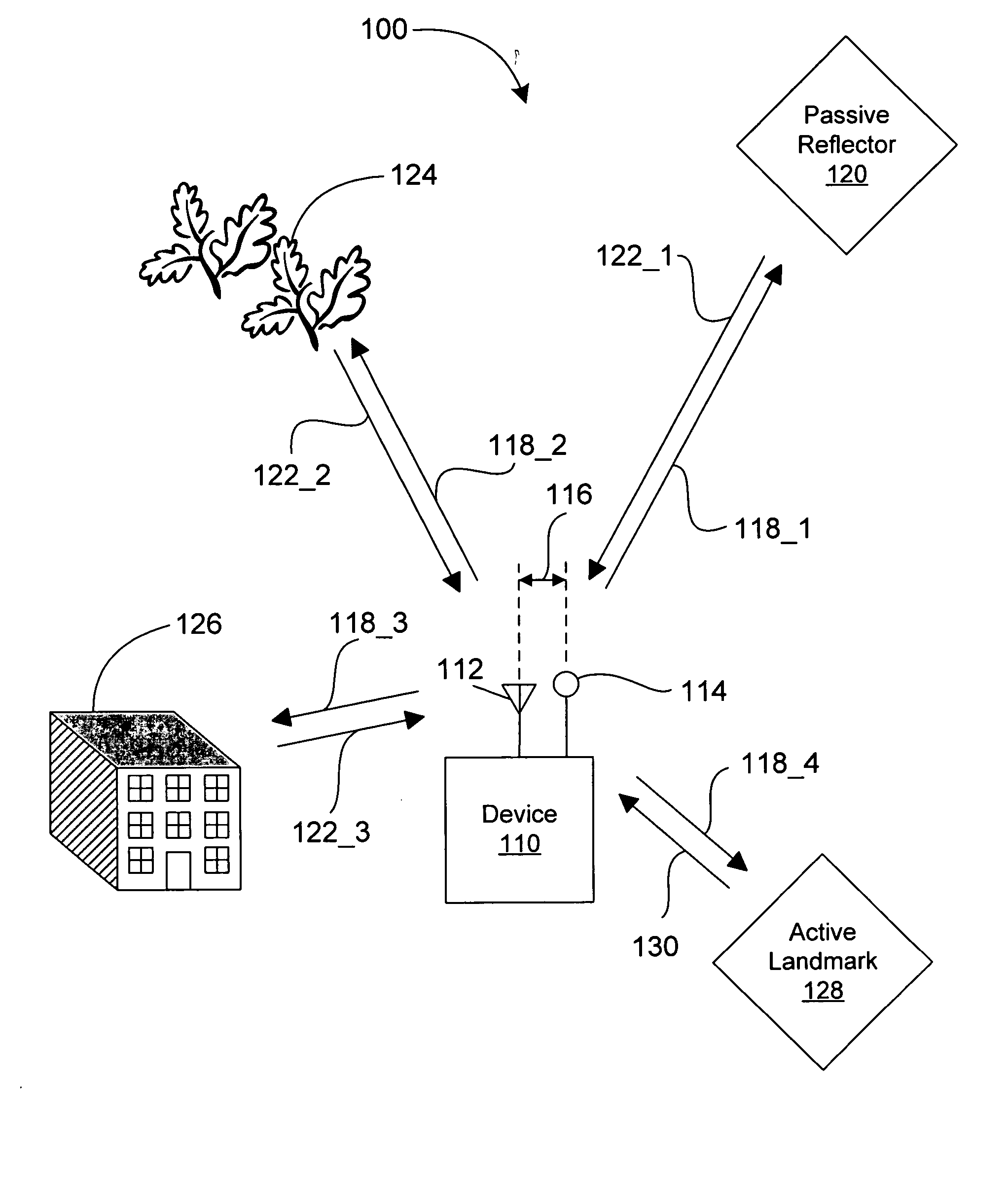
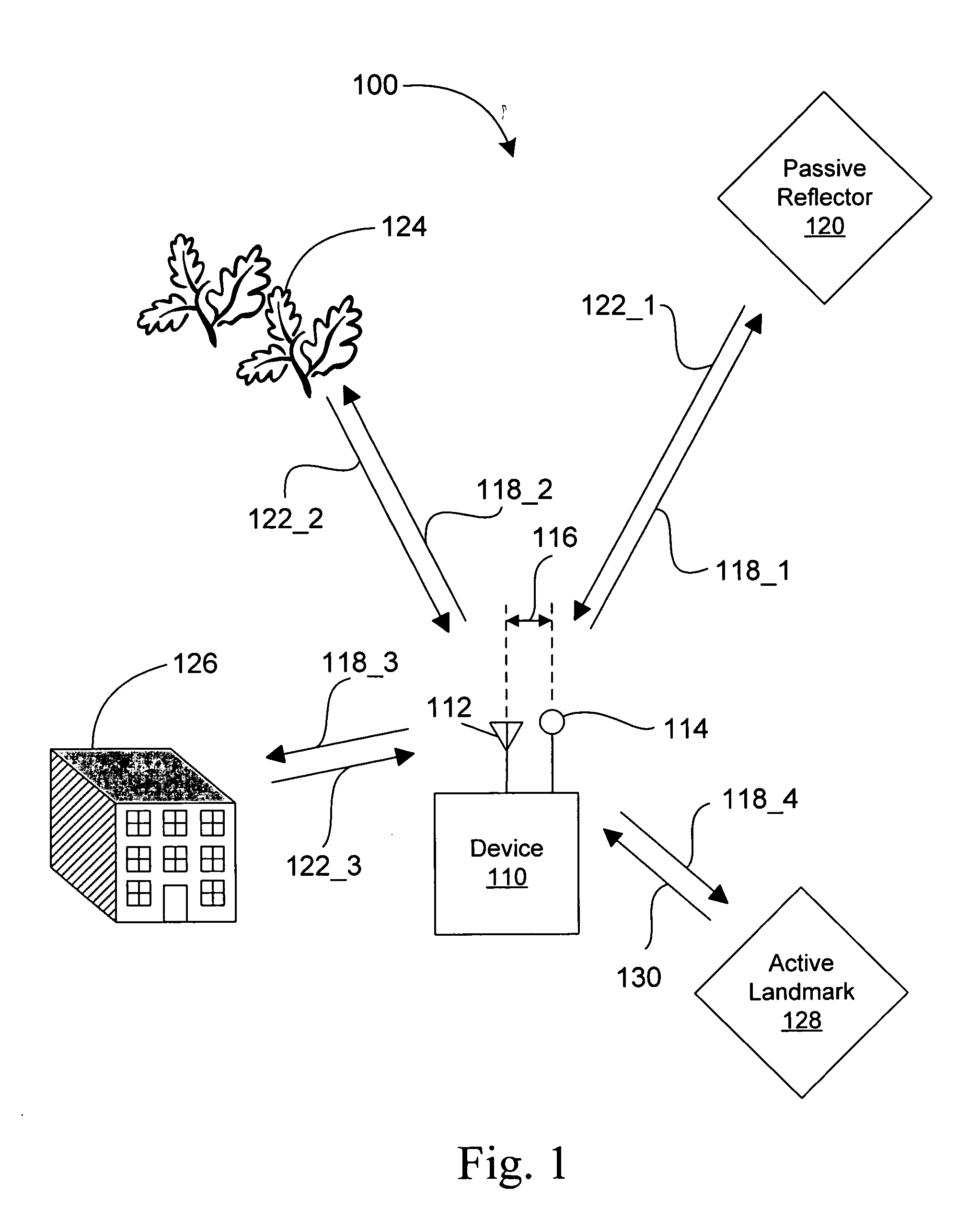
embodiment 100
[0027]FIG. 1 illustrates an embodiment 100 of the positioning system with one or more intentional multi-path signals. A device 110 is configured to transmit one or more signals 118, each of which includes at least one electromagnetic pulse having a carrier signal frequency, using at least one antenna 112. In some embodiments, the device 110 is configured to transmit one or more signals 118 having a plurality of electromagnetic pulses. In an exemplary embodiment, the pulses are 1 nanosecond (ns) in duration and have the carrier signal frequency of 6 gigahertz (GHz). A typical repetition period for the pulses is every microsecond. Other embodiments may employ pulse duration and carrier signal frequency pairings of: 1 ns and 24 GHz; 5 ns and 6 GHz; and 1 ns and 77 GHz. The increased accuracy of range estimation available from shorter pulse durations and higher carrier signal frequencies comes at the expense of increased cost and complexity of associated circuitry in some embodiments.
[0...
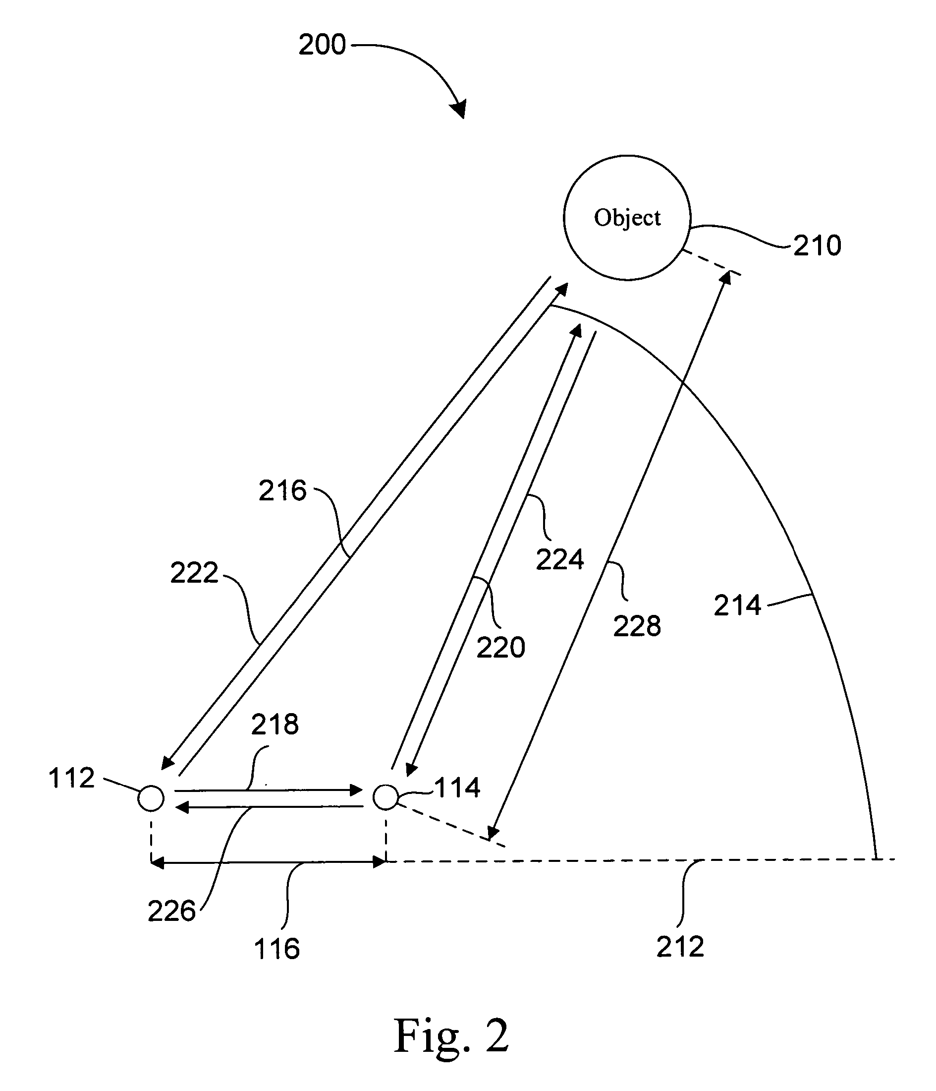
embodiment 200
[0037]FIG. 2 illustrates an embodiment 200 of the positioning system with one or more intentional multi-path signals. Object 210 is at the position with an angle 214 with respect to a line 212 and a direction, such as direction 216, between the antenna 112 (and thus the device 110 in FIG. 1) and the object 210. The antenna 112 transmits a direct-path signal, including at least one electromagnetic pulse having the carrier signal frequency, along the direction 216. The antenna also transmits a signal, including at least one electromagnetic pulse having the carrier signal frequency, along direction 218. The reflector 114 will reflect a first return multi-path signal, including at least one electromagnetic multi-path pulse, along direction 226. A total propagation time for this first return multi-path signal is sufficiently short that, for purposes of determining the position of the object 210, the first return multi-path pulse may be ignored. The reflector 114 will also reflect a multi...
PUM
 Abstract
Description
Claims
Application Information