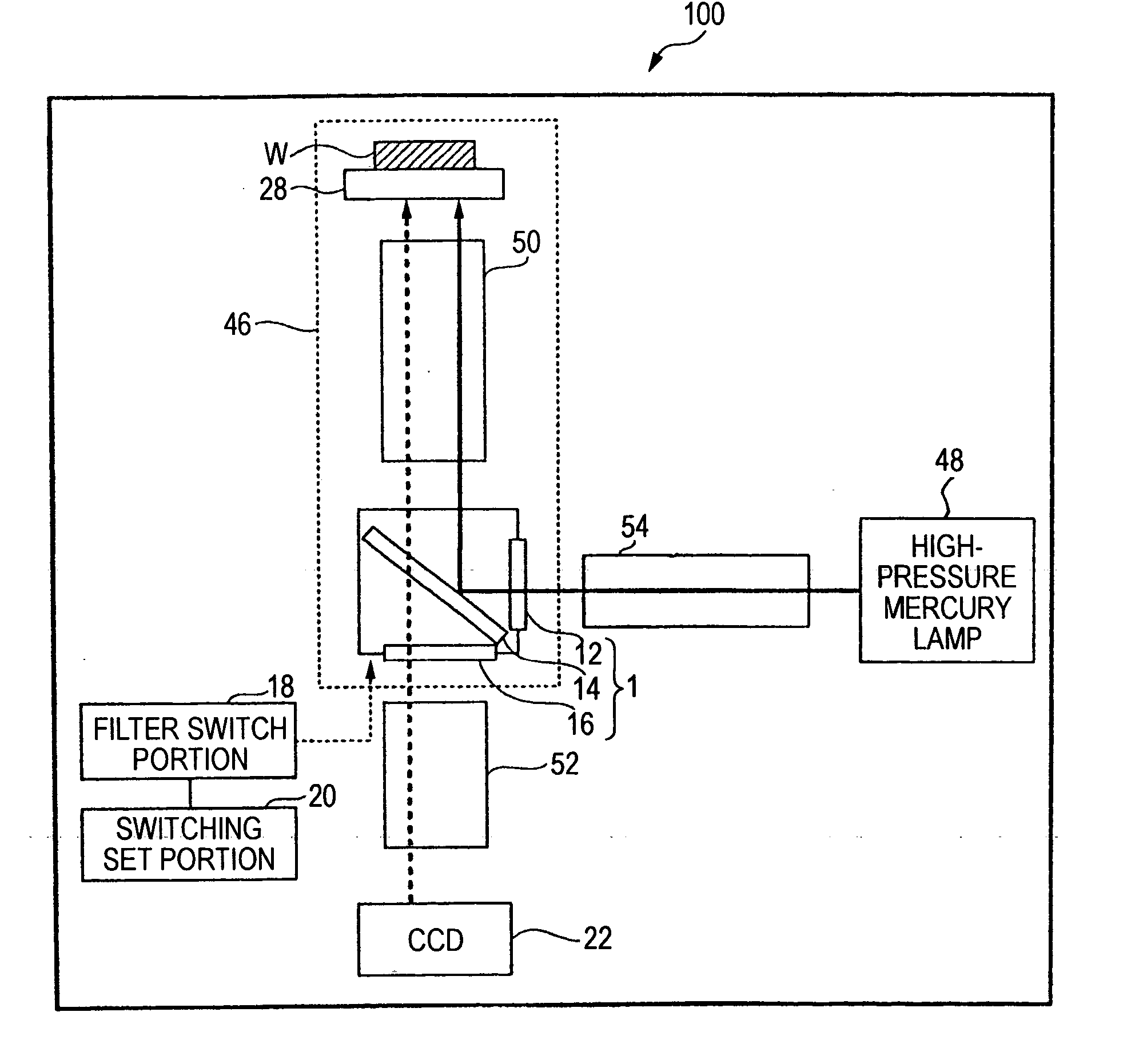
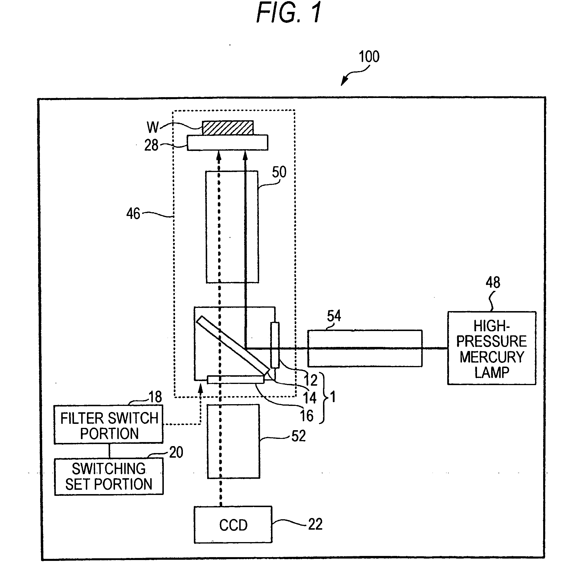
[0010] In order to attain the object, a fluorescence microscope according to the invention comprises: a specimen loading portion for placing a specimen as a target of observation; a filter set including a
excitation filter, a dichroic mirror and an
absorption filter as optical members of an optical
system; a fixed-type objective lens placed between the filter set and the specimen loading portion; a partition for covering at least the specimen loading portion, the objective lens and the filter set to block extraneous light incident on the specimen loading portion; an excitation
light source for emitting an excitation light onto the specimen; an imaging lens arranged on an outgoing surface of the absorption filter of the filter set; and an imaging portion for forming a fluorescent image from a fluorescence emitted from the specimen and received by the imaging lens via the absorption filter by irradiating the excitation light onto the specimen from the excitation
light source via the
excitation filter of the filter set. The imaging lens of the fluorescence microscope includes a
zoom lens capable of continuously changing an operation distance. With this configuration, the fixed-type objective lens is provided to abolish a switching mechanism using a revolver and a slider. This avoids a situation where the tip of the objective lens comes in contact with the specimen or preparation on the specimen loading portion while the objective lens is being replaced, thus damaging the lens or
scratching the lens surface. Use of a
zoom lens changes
magnification without changing the objective lens. In particular, the
zoom lens provides continuous change in magnification, a seamless change in magnification to facilitate a search for the
field of view, unlike the discrete change in magnification by changing an objective lens. A lightproof space is provided by the partition. This allows high-contrast fluorescent image observation with reduced effect of extraneous light. In particular, automatic magnification change using a
zoom lens allows high-picture-quality magnification change maintaining a
high contrast without the lightproof state being impaired by extraneous light at manual change of objective lenses using a revolver.
[0011] Another fluorescence microscope according to the invention further comprises a display portion for displaying the fluorescent image picked up by the imaging portion. This allows a fluorescent image to be observed without providing an
eye lens for
visual observation. This does without a member related to an
eye lens thus simplifying the overall configuration and providing a compact and low-cost fluorescence microscope.
[0013] Another fluorescence microscope according to the invention is characterized in that the fluorescence microscope is an inverted fluorescence microscope. While it is difficult to observe a specimen alive on an upright microscope, it is possible to observe a specimen alive on an
inverted microscope. In general, for the inverted fluorescence microscope, a fluorescence obtained via an objective lens arranged below a specimen in an inverted way needs to be polarized up to the eyes of the observer in upward direction. This introduces a polarization mirror to provide a U-shaped
optical path, thus resulting in a larger-size, more complicated and higher-cost
system. This
disadvantage is offset by abolishing an
eye lens for
visual observation and members for the eye les and a mirror used to change the
optical path, thereby providing a more compact inverted fluorescence microscope.
[0014] Another fluorescence microscope according to the invention is characterized in that the partition has a rectangular shape covering the
optical path of the fluorescence microscope. This allows members of the optical path to be arranged in the rectangular partition in order to maintain the lightproof state without the interference with the optical path by extraneous light.
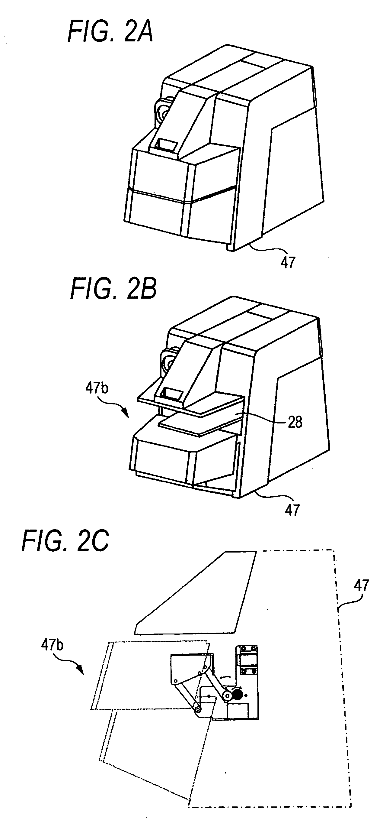
[0015] Another fluorescence microscope according to the invention is characterized in that part of the partition comprises an aperture for
insertion or retrieval of the specimen. This allows the aperture to be opened to place a specimen on the specimen loading portion or replace the specimen. Once the specimen is set, the aperture is blocked so that the inside of the partition will be maintained as a lightproof space thus allowing a specimen to be observed while magnification is being changed at
high contrast.
[0017] According to the fluorescence microscope of the invention, it is possible to observe a fluorescent image at high contrast by shielding light to a specimen from outside, without placing the specimen in a darkroom. This further prevents excessive
fading. Further, a related art fluorescence microscope requires manual switching between objective lenses using a revolver or a slider to change magnification and the lightproof space is impaired each time the magnification is changed thus degrading the contrast as well as change in magnification is cumbersome. Further, extreme care must be exercised in switching between objective lenses so as not to damage a specimen with the objective lens. With the fluorescence microscope of the present invention, use of a
zoom lens has enabled automatic magnification change. Once a specimen is set and a lightproof space provided, magnification change is made easy while maintaining the lightproof state. This provides an excellent
advantage that safe and high-picture-quality observation is possible while maintaining high contrast and without the contact of the objective lens with the specimen in changing modification, due to the fixed-type objective lens.

