
Asymmetric packet switch and a method of use

a packet switch and asymmetric technology, applied in the field of network switching technology, can solve the problems of low-end switches, limited flexibility, unmanaged packets, and no information, and achieve the effects of low cost, not expensive, and saving development costs

Active Publication Date: 2005-12-08
GIGAMON
View PDF14 Cites 86 Cited by
  • Summary
  • Abstract
  • Description
  • Claims
  • Application Information

AI Technical Summary

Benefits of technology

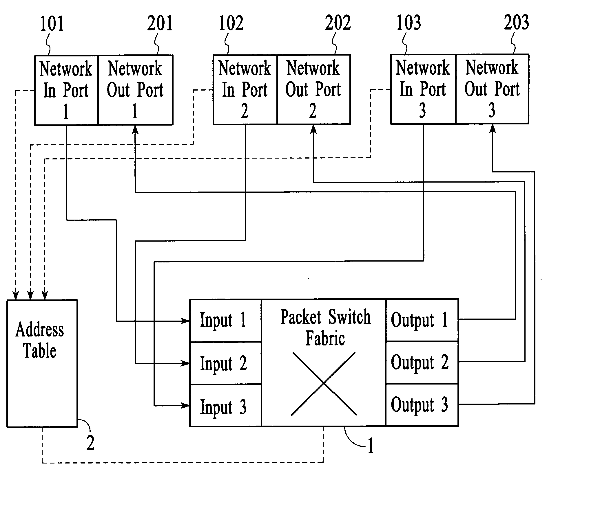
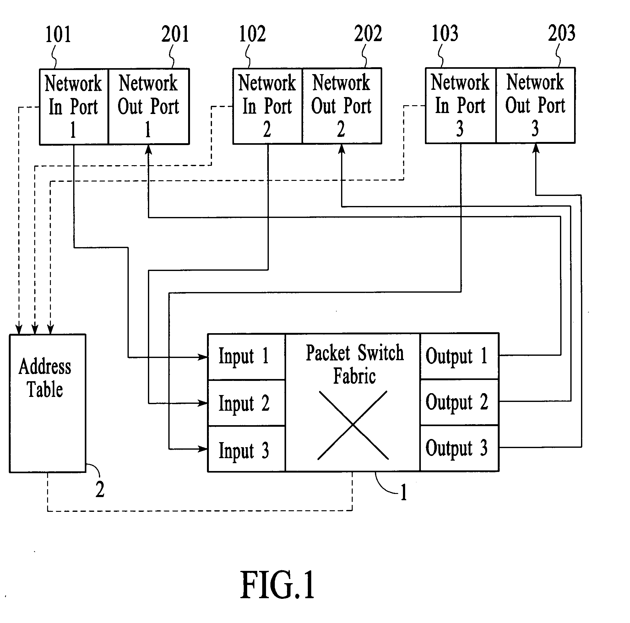
[0049] A system and method in accordance with the present invention presents a low cost implementation of the asymmetric packet switch. The advantages of using a commercial off-the-shelf packet switches is that the chip has been debugged by the vendor and that nowadays such switches are not expensive. Moreover, the high-end packet switch has significant functionality, including, but not limited to, filtering based on L2 / L3 / L4 information, quality of service (QoS), link aggregation, VLAN support, double VLAN tagging, spanning trees and per-VLAN spanning tree support and stacking of multiple chips. The key feature of the present invention is configuring a switch so that it has a set of network ports and a set of instrument ports, and that packets flowing from the network ports to the instrument ports go through a circuit switch, whereas at the same time packets flowing from an instrument port to a network port go through a packet switch.
[0050] In summary, a system and method in accordance with the present invention (1) saves development cost compared with developing FPGA and ASIC, (2) saves development time (including debugging time for ASIC and FPGA), (3) provides a reliable solution because the commercial layer 2 / 3 switches have been tested and have been used by quite a number of switch system vendors; and (4) leverages on the advanced functionalities of the current layer 2 / 3 switches.

Problems solved by technology

These unmanaged packet switches are generally low-end switches because they offer very limited flexibility and provide no information such as packet statistics to the user.
As before mentioned packet switches are utilized extensively in networks; however, they present problems when trouble shooting a network.
Overall the cost of ownership is high and the equipment takes up much space.
Both the sniffer and the RMON probe are expensive devices.
There are not that many monitoring ports available per unit, making the cost per port ratio extremely high.
This situation is worse if the user has an extensive network that spreads over broad geographical locations, such as over several floors in a company building.
In order to cover all the strategic sections of the network, the user has to install a sniffer or a RMON probe at every strategic section, making the cost of ownership extremely high.
More importantly, the user still cannot get an aggregated, simultaneous view of the traffic going through the different segments.
Most network monitoring devices, protocol analyzers and RMON probes do not have hardware filtering capability.
This restriction is particularly problematic when filtering at line speed on high speed links.
However, because every port sees the traffic of every other port, a hub utilizes a significant amount of bandwidth.
The problem of bandwidth usage leads to the use of a packet switch in a network.
However, this becomes problematic for network monitoring and trouble-shooting because no matter which port in the switch the user plugs the sniffer into, the sniffer cannot see all the relevant traffic in the network.
This is somewhat better but the network visibility is still not as good when compared with using a hub.
Another drawback of using a span port is that one user of the switch may alter the span port settings created by another user without letting the other user know.
For example, in a company the network security people may use the span port to look at traffic at port X, and then in the middle of the night the IT people may come and change the span port settings to look at traffic at port Y. Though a lot of times this is not intentional, mistakes do occur and this may lead to severe negative impacts.
The drawback of this is that there is another layer of infrastructure that the user needs to set up, increasing the cost of ownership as well as taking up valuable space in the IT area.
First, these distributed sniffers do not stream the monitored or captured packets to a centralized location.
Second, there is no real-time aggregation of packets collected over multiple network segments to a central area and this is not helpful for VoIP monitoring and trouble-shooting.
It is also very expensive to overlay a separate network just to connect all these distributed sniffer units.
This utilizes a significant amount of bandwidth of the user's network.
In any case the deployment of IDS or IPS presents the same set of problems as with the deployment of network monitoring devices (see items 1 through 4 above).

Method used


Image

  • Asymmetric packet switch and a method of use
  • Asymmetric packet switch and a method of use
  • Asymmetric packet switch and a method of use

Examples


first embodiment

ets within the Network Visibility System

[0114] One-to-One: Ingress packets at one port are provided to another port. Typically, this involves taking ingress packets at a network port and egress out of an instrument port. However, one-to-one can also be used for port-pairing, that is, traffic entering a network port is sent out of another network port, and vice versa, making these two network ports form a port-pair.

[0115] There are three different methods to implement one-to-one.

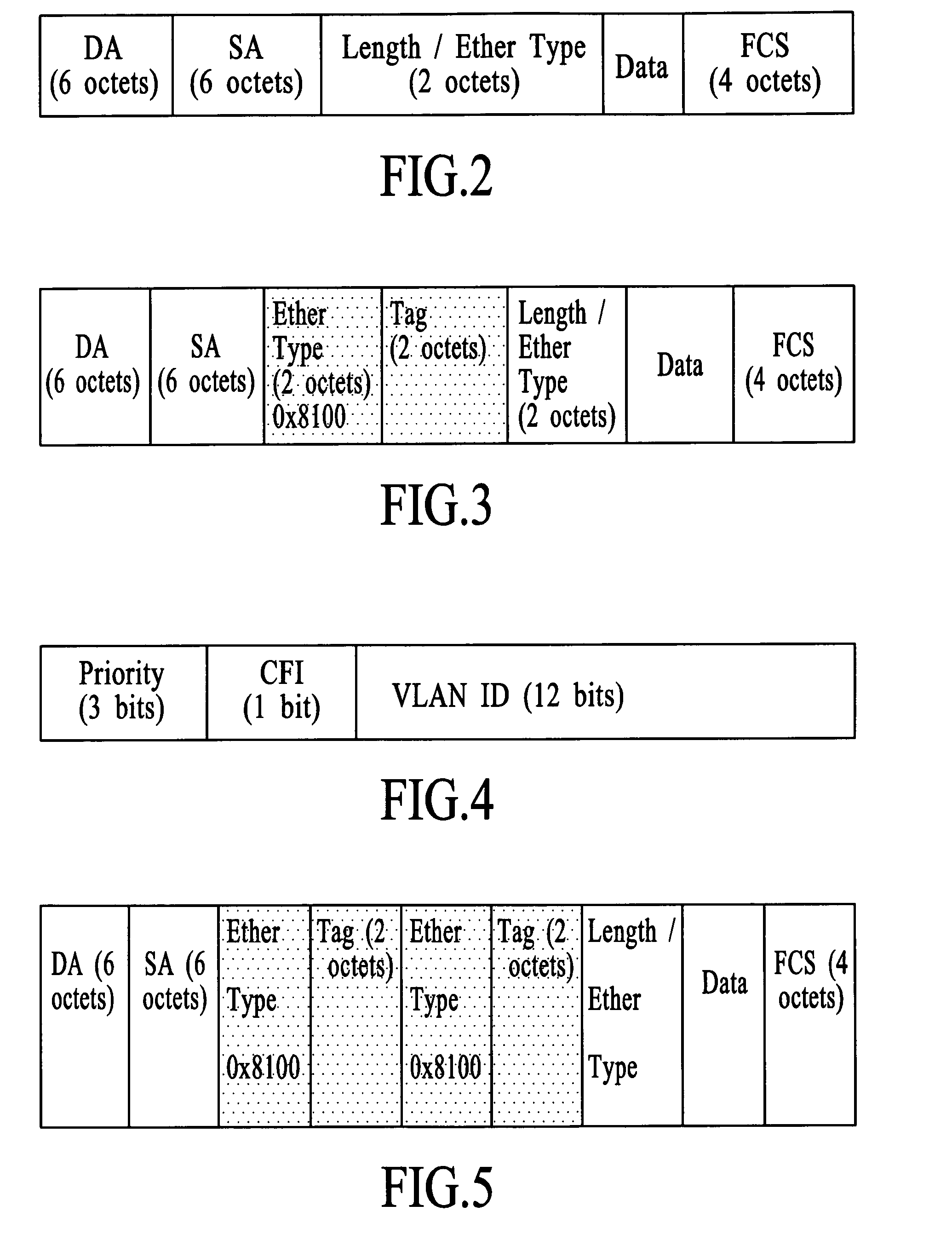
[0116] The first method involves using a virtual local area network (VLAN) identifier to direct the packets. A VLAN is created with membership having only the two ports involved in this one-to-one connection. For example, suppose the VLAN number for this VLAN is X. The ingress port is set up such that the default VLAN ID is X. With this setting, all packets entering the ingress port will be tagged with a VLAN tag having VLAN number X. All such ingress packets will be flooded out of the second port, hence fo...

second embodiment

[0150] There are two kinds of filters supported in the network monitor: pre-filter and post-filter.

[0151] The packet switch allows packet filtering on a per port basis at the ingress direction.

[0152] A filter can selectively pass or drop an ingress packet based on the filtering criteria. A filtering criterion is set up by the user and can be based on the L2 / L3 / L4 packet content together with a bit mask.

[0153] Pre-filter is a direct application of the ingress filtering capability of the packet switch. Hence pre-filter applies the filter to all ingress packets at a given port, independent of their egress ports. There are situations in the network visibility system where packets entering an ingress port are multicasted out to multiple instrument ports. Each instrument port may want to see a different filtered subset of this packet stream. For example, in FIG. 13, a traffic stream composed of HTTP, TCP and UDP traffic enters network port 1301. The user may set up the network monitor ...

third embodiment

ming and Load Balancing

[0163] In flow-based stream, traffic from one or more network ports is connected to one or more instrument ports. The goal is to have each instrument port receive a different flow of the traffic. A flow can be characterized by a number of criteria, including, but not limited to, a connection between a pair of source and destination IP addresses, a connection between a pair of TCP port numbers within an IP connection, or some other connections specified by certain specific network protocol parameters.

[0164] One method of implementing flow-based stream using a conventional packet switch is to use the link aggregation (trunking) capability of the switch. (Reference: IEEE 802.1ad). In a link aggregation configuration, multiple ports are bundled together into a logical port. Traffic that egresses out of this logical port is distributed to its member ports according to a deterministic hashing algorithm which can be based on the L2, L3 and L4 information of the pack...


PUM


Abstract

The present invention relates to a packet switch and a packet switching method. An example embodiment of the present invention comprises at least three network ports, at least one instrument port, a mux-switch, a packet switch fabric, and an address table. The embodiment updates the address table to include the source address of each ingress packet of each network port and associate the source address with that network port. The mux-switch routes the ingress packet traffic of each network port according to the identity of the network port so that at least a copy of the packet traffic of one of the network ports is routed to an instrument port. The packet switch fabric routes the packets from the instrument ports to the network ports according the destination address of the packet and the identity of the network port that is associated with the destination address as recorded in the address table.

Description

CROSS-REFERENCE [0001] This application claims priority to U.S. Provisional Application Ser. No. 60 / 568,310, filed May 5, 2004, which is incorporated herein by reference in its entirety. RELATED APPLICATIONS [0002] This application is related to the following co-pending applications: [0003] application Ser. No. ______ (Attorney Docket No. 3591P), entitled “Asymmetric Packet Switch and Method of Use,” filed on even date herewith. [0004] application Ser. No. ______ (Attorney Docket No. 3592P), entitled “Asymmetric Packet Switch and Method of Use,” filed on even date herewith [0005] application Ser. No. ______ (Attorney Docket No. 3593P), entitled “Asymmetric Packet Switch and Method of Use,” filed on even date herewith. INCORPORATION BY REFERENCE [0006] All publications and patent applications mentioned in this specification are herein incorporated by reference to the same extent as if each individual publication or patent application was specifically and individually indicated to be ...

Claims


Application Information

Patent Timeline
Patent Type & Authority Applications(United States)
IPC IPC(8): H04L1/00H04L12/24H04L12/26H04L12/28H04L12/46H04L12/56H04L29/06
CPCH04L12/4645H04L41/0213H04L41/046H04L41/0896H04L43/028H04L43/0823H04L43/0882H04L43/12H04L43/16H04L43/18H04L49/201H04L49/351H04L49/354H04L49/555H04L63/0227H04L63/1408H04L12/4641
Inventor GALLATIN, TOMMIU, DENNY K.WON, KING L.LEONG, PATRICK PAK TAKHO, TED
Owner GIGAMON
Learn More