
Apparatus and method for ignition of high-gain thermonuclear microexplosions with electric-pulse power
a technology of thermonuclear microexplosion and electric pulse, which is applied in nuclear engineering, nuclear reactors, greenhouse gas reduction, etc., can solve the problems of low efficiency, heavy burden, and not much gain
- Summary
- Abstract
- Description
- Claims
- Application Information
AI Technical Summary
Benefits of technology
Problems solved by technology
Method used
Image

Examples
Embodiment Construction
[0018] Those of ordinary skill in the art will realize that the following description of the present invention is illustrative only and not in any way limiting. Other embodiments of the invention will readily suggest themselves to such skilled persons.
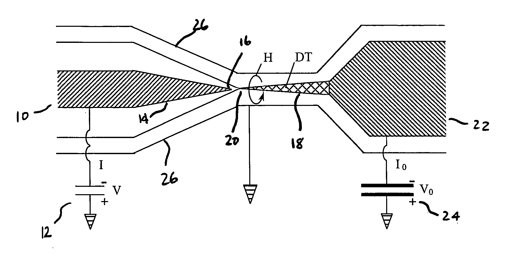
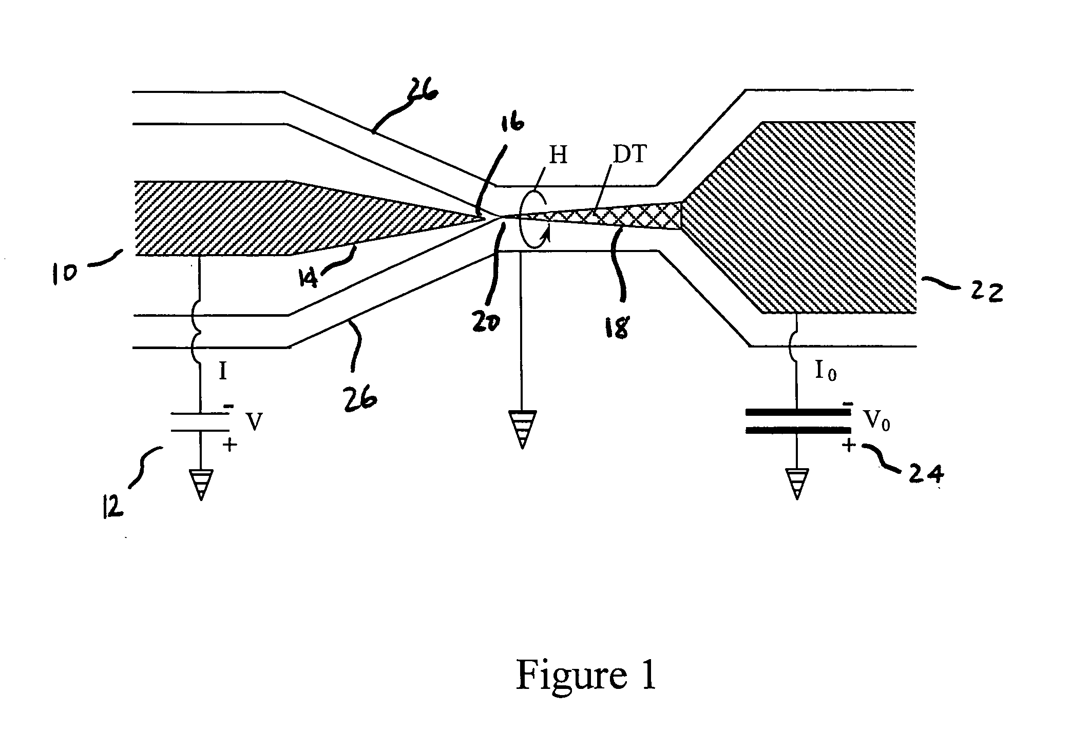
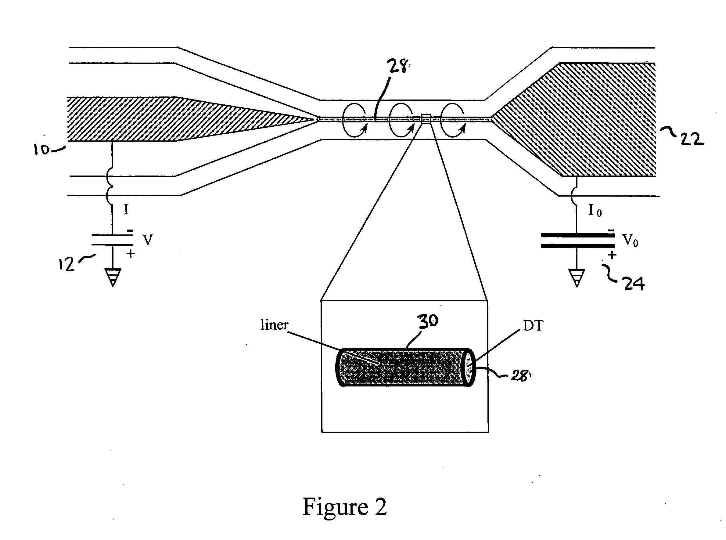
[0019] The basic principle of the concept can be explained for the special configuration of two nested magnetically insulated transmission lines as shown in FIG. 1. An inner transmission line 10 is coupled to a first high-voltage high-current pulse source 12, such as a Marx generator. The inner transmission line 10 ends in a cone 14 with the tip 16 of the cone serving as a cathode for a field emitted intense relativistic electron beam. The return current conductor of the inner transmission line 10 is at its smaller diameter connected to a cone of solid DT 18, serving as the anode of the inner transmission line 10, transmitting a pulse of voltage V and current I.
[0020] An intense relativistic electron beam emitted from the cathode tip...
PUM
 Abstract
Description
Claims
Application Information