Target detection system using radar and image processing

a detection system and target technology, applied in the field of target detection system, can solve the problems of low detection accuracy of a far target, low detection accuracy of a near target, and erroneous recognition, so as to prevent erroneous recognition, reduce detection time, and improve reliability

Inactive Publication Date: 2005-12-08
FUJITSU GENERAL LTD
View PDF12 Cites 2 Cited by
  • Summary
  • Abstract
  • Description
  • Claims
  • Application Information

AI Technical Summary

Benefits of technology

[0014] An object of the present invention is to provide a target detection system using the EHF radar and image processing, wherein the processing time for detection is shortened while compensating for the disadvantages of the EHF radar and image processing with each other.
[0015] Another object of the invention is to provide a target detection system using both the EHF radar and the image processing, wherein the reliability is improved by preventing erroneous recognition and erroneous distance measurement in image recognition processing.
[0016] The present invention has been developed in order to achieve the objects described above. According to one aspect of the invention, there is provided a target detection system comprising a radar, an image acquisition unit and a processing unit. The processing unit specifies an area for image recognition based on the data output from the radar, and processes image data output from the image acquisition unit only within the specified area thereby to detect a target. According to this invention, objects other than three-dimensional ones, including lines or letters on the road surface are not detected by the radar as a target, and therefore lines, letters and other auxiliary objects are not detected as a target by image processing. Also, the image data are processed only for an area where a target such as an obstacle or a vehicle is detected by the radar, and therefore the time required for processing the image data is shortened thereby shortening the processing time, as a whole, for target detection.
[0017] In the target detection system according to this invention, the image recognition area can be specified based on the power of the signal output from the radar. Upon detection of a target such as an obstacle or a vehicle, the radar outputs a signal of predetermined power. A target is extracted only from an area having such a target by extracting the edge of the image data only for the particular area from which the signal power is detected. As a result, the time required for image data processing can be shortened. By the way, all the edges may be extracted from the image data and only the edges existing in the image recognition area may be processed as effective edges for target detection. In such a case, the time required for image processing is not shortened but the time required for fusion processing can be shortened.
[0018] In the target detection system according to this invention, the image recognition area can be determined based on the state of the near flag output from the radar. Upon detection of a near target, the radar outputs a near flag, the state of which changes with the distance to the target. In the processing for target detection, the edge data acquired in the image processing is selected in accordance with the presence or absence and the state of the near flag, and therefore the recognition error and the distance measurement error of the target can be prevented before the fusion processing.
[0019] Further, in the target detection system according to this invention, a road surface flag and a letter flag can be attached to the edge data extracted by image processing in the case where a density difference on the image due to lines or letters on the road surface is detected. For the edge data with the road surface flag or the letter flag, it is determined whether the edge data including the particular road surface flag or the letter flag actually represents lines or characters written on the road surface. In the case where the edge data are found to represent lines or letters, the data in the particular area is invalidated. As a result, the recognition error in which lines or characters on the road surface are recognized as a target and the measurement error can be prevented before the fusion processing.

Problems solved by technology

The EHF radar can measure a far distance with high accuracy but is low in accuracy for the measurement of a near target.
Image processing can be used to measure the distance over a wide range but is low in accuracy for detection of a far target.
(Erroneous recognition) In view of the fact that the edge extraction processing is for simply extracting the edges from an image, the edges of letters written on the road surface, shadows or other objects not three-dimensional and different from the target may be extracted erroneously due to the density difference thereof.
In this processing, the result may become erroneous in the case where a similar pattern happens to exist.
In the conventional target detection system, the processing time for the fusion algorithm in the fusion processing microcomputer is required in addition to the processing time for the EHF radar and the processing time for the image processing microcomputer, and therefore the total processing time is long.
Also, the conventional target detection system has yet to overcome the disadvantages of both the EHF radar, and image processing, sufficiently.

Method used


Image

  • Target detection system using radar and image processing
  • Target detection system using radar and image processing
  • Target detection system using radar and image processing

Examples


embodiment 1

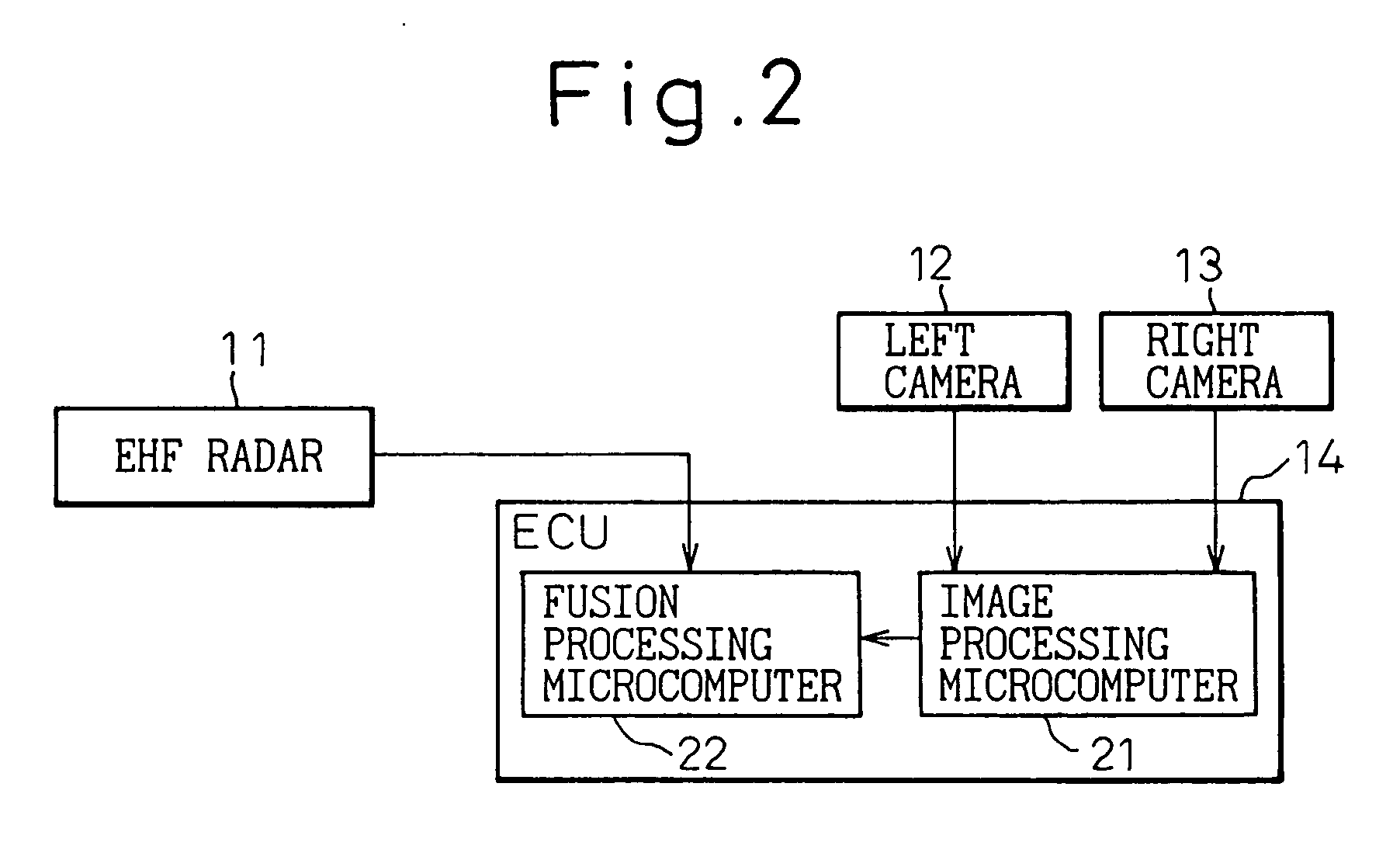
[0057]FIG. 7 shows a vehicle target detection system according to a first embodiment of the invention.

[0058] A vehicle target detection system comprises an EHF radar 11, a left camera 12, a right camera 13 and an image processing ECU 14. The ECU 14 is configured with a microcomputer 15 having the dual functions of image processing and fusion processing. Although the two cameras 12, 13, left and right, are used for measuring the distance by parallax in image processing, only one camera will do in the case where the distance is not measured by parallax.

[0059] Now, the processing in the microcomputer 15 will be explained.

embodiment 1-1

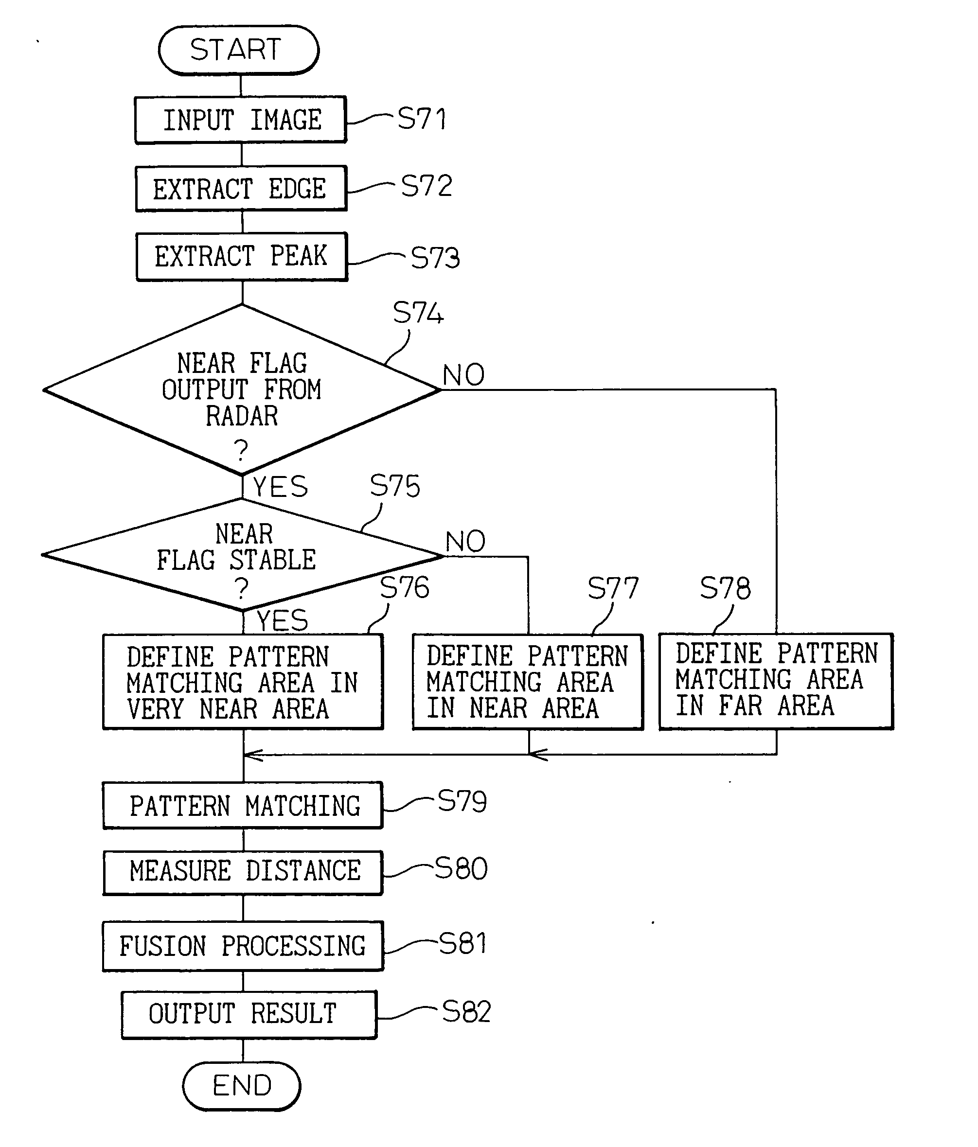
[0060]FIG. 8 is a flowchart showing the processing in the microcomputer 15. The condition ahead of the vehicle is assumed to be the same as shown in FIG. 3 and described above.

[0061] In FIG. 8, the interior of a specified area is scanned by the EHF radar 11 in step S1. FIG. 9 shows the result of scanning obtained from the EHF radar 11. In FIG. 9, the abscissa represents the horizontal position (angle) of the area scanned, and the ordinate the power strength in dB. In the case where a preceding vehicle 6 is present, as shown, the signal power strength is high at the horizontal position corresponding to the preceding vehicle 6.

[0062] In step S2, an object having a high signal power strength (not less than P dB) is recognized as a target, and the range (X0 to X1) where the target is present is held as a search area. In the case shown in FIG. 3, what is detected as a target is the preceding vehicle 6 alone. Power is not detected from a planar object like the lines 7 drawn on the road ...

embodiment 1-2

[0069] The detection of the search area in Step S2 of FIG. 8 can be variously modified.

[0070]FIG. 11 shows a different method of extracting the search area in step S2. FIG. 12 shows the result of this edge extraction. In FIG. 11, the range of first level P0 to second level P1 dB of the signal power strength obtained from the EHF radar 11 is defined as a predetermined level range of power strength, and the ranges X0 to X1, X2 to X3 in the particular level range are extracted as a search area. The portion of FIG. 11 where the power strength is high represents the detection of a target. The range of P0 to P1 dB where the signal power strength changes sharply represents the edge position of the target. According to this embodiment, therefore, the position where the edges can probably be extracted can be further limited, and therefore, as shown in FIG. 12, only the edges of the target can be extracted, thereby further shortening the processing time.


PUM


Abstract

A target detection system using an EHF radar and the image processing is disclosed, in which the processing time is shortened by mutually complementing the disadvantages of the EHF radar and the image processing thereby to improve the reliability. The system comprises a radar, an image acquisition unit and an image processing ECU. The microcomputer of the ECU specifies an image recognition area based on the power output from the radar, and carries out the image processing only within the specified recognition area for the image obtained from the image acquisition unit. By performing the image processing only for the area where a target is detected by the radar, the time required for image processing is shortened on the one hand and the erroneous detection of letters on the road surface or the like is eliminated.

Description

CROSS-REFERENCE TO RELATED APPLICATION(S) [0001] This application is a divisional of U.S. application Ser. No. 09 / 834,403, filed Apr. 13, 2001, which claims priority of Japanese patent Application No. 2000-118549, filed Apr. 14, 2000, and Japanese patent Application No. 2000-152695, filed on May 18, 2000, priority of which are claimed herein.BACKGROUND OF THE INVENTION [0002] 1. Field of the Invention [0003] The present invention relates to a target detection system. The target detection system according to this invention is mounted on an automotive vehicle, for example, and is used to aid the driver in driving the vehicle by detecting a preceding vehicle running ahead of his vehicle or an obstacle lying ahead or the like target located ahead of the vehicle driven by the driver. [0004] 2. Description of the Related Art [0005] A conventional target detection system uses a fusion algorithm in which the reliability of data is studied by use of the result of detecting a target using a E...

Claims


Application Information

Patent Timeline
Patent Type & Authority Applications(United States)
IPC IPC(8): G01C3/08G01C11/06G01S7/41G01S11/12G01S13/86G01S13/931G06T7/00G06V10/25
CPCG01C3/08G01C11/06G01S7/41G01S11/12G01S13/931G06K9/3233G01S13/867G06T7/97G06V10/25
Inventor OHTA, AKIHIROOKA, KENJI
Owner FUJITSU GENERAL LTD
Why Eureka
Try Eureka