Wireless communication apparatus

a communication apparatus and wireless technology, applied in multiplex communication, electromagnetic wave modulation, high-level techniques, etc., can solve the problems of fluctuation in operating output power, degradation in power added efficiency of transmission amplifiers, etc., and achieve the effect of improving the power added efficiency of transmission power amplifiers

Inactive Publication Date: 2005-12-08
SHARP KK
View PDF20 Cites 25 Cited by
  • Summary
  • Abstract
  • Description
  • Claims
  • Application Information

AI Technical Summary

Benefits of technology

[0029] In view of the problem described above, it is an object of the present invention to provide a wireless communication apparatus that can achieve improvement in the power added efficiency of a transmission power amplifier.
[0034] Therefore, in each of the transmission amplifiers, the fluctuation in the operating output power between when the transmission method is used and when it is not used is controlled smaller than that in the conventional example, thereby achieving the improvement in the efficiency of each of the transmission amplifiers.
[0042] At this point of time, the backoff decreases and the efficiency of each of the transmission amplifiers further improves by, while maintaining the operating output power of the transmission amplifiers at the same value, controlling the saturation output power of the transmission amplifier included in each of the plurality of transmission systems smaller than the saturation output power adopted when the transmission method is used.
[0044] For example, in transmitting the single unit of data without use of the transmission method, the N subcarriers may be dispersed for the allocation so as to minimize variation in the number of the subcarriers allocated among the plurality of the transmission systems.
[0045] This achieves more optimized improvement in the efficiency of each of the transmission amplifiers.

Problems solved by technology

In the conventional example, using a transmission amplifier so as to provide the transmission power at the upper limit in both cases where the transmission method is used and where it is not used has resulted in degradation in the power added efficiency of the transmission amplifier.
This degradation is attributable to one transmission amplifier outputting the transmission power at the upper limit, which has caused fluctuation in the operating output power of the transmission amplifier between when the transmission method is used and when it is not used.

Method used


Image

  • Wireless communication apparatus
  • Wireless communication apparatus
  • Wireless communication apparatus

Examples


first embodiment

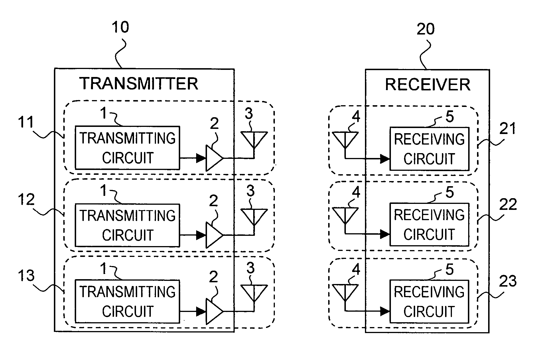
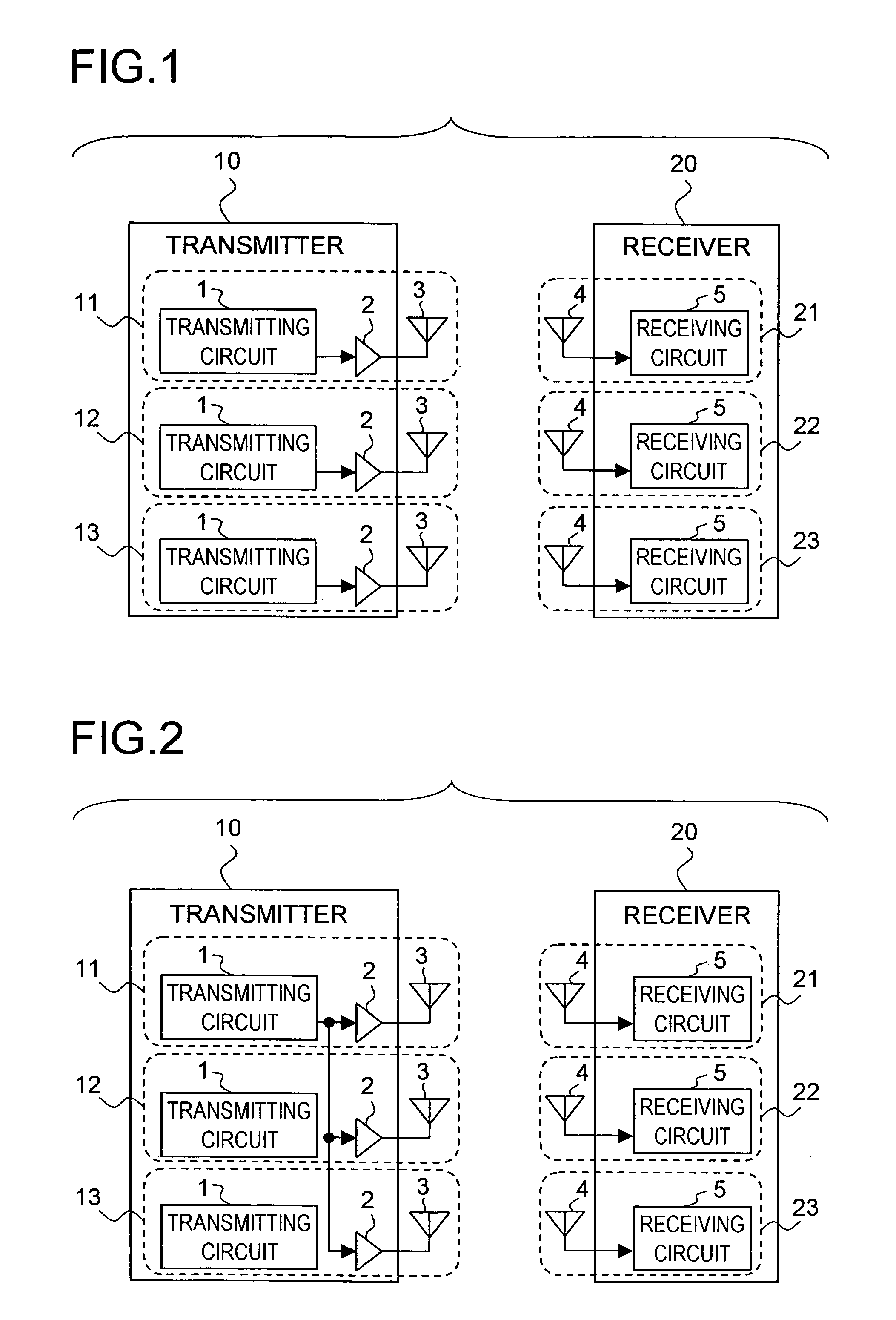
[0057] A first embodiment of a wireless communication apparatus according to the present invention will be described below with reference to the accompanying drawings. FIG. 1 is a block diagram showing the configuration of the wireless communication apparatus according to the first embodiment. In FIG. 1, portions corresponding to those shown in FIG. 7 are provided with the same numerals, and thus description of some of the details thereof may be omitted. The wireless communication apparatus in FIG. 1 includes a transmitter 10 and a receiver 20.

[0058] The transmitter 10 includes three transmission systems: the first transmission system 11 (hereinafter sometimes simply referred to as “transmission system 11”); the second transmission system 12 (hereinafter sometimes simply referred to as “transmission system 12”); and the third transmission system 13 (hereinafter sometimes simply referred to as “transmission system 13”). Each of the transmission systems 11, 12, and 13 roughly include...

second embodiment

[0080] Next, the second embodiment of a wireless communication apparatus according to the present invention will be described below with reference to the accompanying drawings. The configuration of the wireless communication apparatus according to the second embodiment is the same as that of the wireless communication apparatus of the first embodiment; therefore, it is omitted from the description. Moreover, the MIMO operation in the second embodiment is the same as that in the first embodiment. The wireless communication apparatus of the second embodiment is different from the wireless communication apparatus of the first embodiment in that, when the OFDM modulation method is adopted in the non-MIMO operation, the method of dispersing the power is further optimized.

[0081] Thus, the non-MIMO operation, the unique feature of this embodiment, will be described below. The configuration of the wireless communication apparatus of this embodiment in the non-MIMO operation is the same as ...

third embodiment

[0092] The second embodiment described above is widely applicable to communication systems that handle a multicarrier signal including two or more subcarriers, and not limited to the OFDM modulation method. Hereinafter, a modification of the second embodiment in a case where a VSF-CDMA method is adopted will be described as the third embodiment.

[0093]FIG. 6 schematically shows the spectrum of a signal transmitted from the transmitter 10 when the VSF-CDMA method is adopted. This signal is formed by arranging on the frequency axis two carriers' worth of spectra 61 and 62 that correspond to a CDMA signal having a band width of 20 MHz, thus having a total band width of 40 MHz. The VSF-CDMA method is also one type of multicarrier transmission methods that divide data to be transmitted into a plurality of carrier waves for transmission. The data to be transmitted is transmitted as a multicarrier signal having the two divided subcarriers (61, 62).

[0094] When the signal as shown in FIG. 6...


PUM


Abstract

In a wireless communication apparatus which is provided with three transmission systems each including therein a transmission power amplifier for amplifying a signal received and a transmitting antenna for transmitting the amplified signal and which is applicable to an MIMO transmission method for simultaneously transmitting three units of data having mutually different contents, in transmitting single unit of data without use of the MIMO transmission method, power of a transmission signal is dispersed for the transmission by simultaneously transmitting same signals from the transmitting antennas corresponding to the transmission power amplifiers by use of the three transmission power amplifiers included in the three transmission systems.

Description

[0001] This application is based on Japanese Patent Application No. 2004-165729 filed on Jun. 3, 2004, the contents of which are hereby incorporated by reference. BACKGROUND OF THE INVENTION [0002] 1. Field of the Invention [0003] The present invention relates to a wireless communication apparatus that transmits data from a transmitter to a receiver by wireless, and particularly to a wireless communication apparatus employing a Multiple Input Multiple Output (MIMO) transmission method. [0004] 2. Description of Related Art [0005] In recent years, more and more wireless communication apparatuses are provided with a plurality of systems each including an antenna, and a transmitting and a receiving circuits. Examples of such wireless communication apparatuses include wireless communication apparatuses employing so-called a diversity reception method that includes two or more reception systems while including only one transmission system. Of these wireless communication apparatuses, part...

Claims


Application Information

Patent Timeline
Patent Type & Authority Applications(United States)
IPC IPC(8): H04B7/06H04B1/04H04B1/02H03C7/02H04B7/04H04J99/00H04B7/02
CPCH04B7/0613Y02D70/444Y02D70/142H04B7/0697Y02D30/70
Inventor AMANO, YOSHIHISA
Owner SHARP KK
Why Eureka
Try Eureka