
Video processing methods for improving visual acuity and/or perceived resolution

a video processing and visual acuity technology, applied in the field of visual acuity and/or perceived resolution improvement, can solve the problem of limiting the resolution of an image that can be imparted to the patient's brain, and achieve the effects of reducing the density of electrodes, and improving visual acuity

Inactive Publication Date: 2005-12-08
SECOND SIGHT MEDICAL PRODS
View PDF3 Cites 14 Cited by
  • Summary
  • Abstract
  • Description
  • Claims
  • Application Information

AI Technical Summary

Benefits of technology

"The present invention is about improving visual acuity for patients with retinal or age-related macular degeneration by using a retinal prosthesis that stimulates neural pathways in the patient's retina. The invention proposes a video processing technique that uses a high resolution optical input device to provide a video signal, which is then processed to select and stimulate subsets of pixels. The video processor selects subsets of the input pixels and processes them to determine an output pixel value for each selected subset. A low resolution video output device then generates a pixelated image with a resolution of no more than one-fourth of the image resolution available from the high resolution optical input device. The display driver then drives the pixels in the low resolution video output device in response to the output pixel values. The invention also includes techniques for altering the processing algorithm to improve the resolution of the image and stimulate virtual electrodes at locations physically displaced from the stimulation electrodes. The technical effects of the invention include improving the resolution of the image and enhancing the perceived visual acuity of patients with retinal or age-related macular degeneration."

Problems solved by technology

Each of these structures potentially suffer from resolution problems that, for the foreseeable future, significantly limit the density of electrodes at the patient's brain or retina that may stimulated and thus limit the resolution of an image that can be imparted to the patient's brain.

Method used


Image

  • Video processing methods for improving visual acuity and/or perceived resolution
  • Video processing methods for improving visual acuity and/or perceived resolution
  • Video processing methods for improving visual acuity and/or perceived resolution

Examples


exemplary embodiment 50

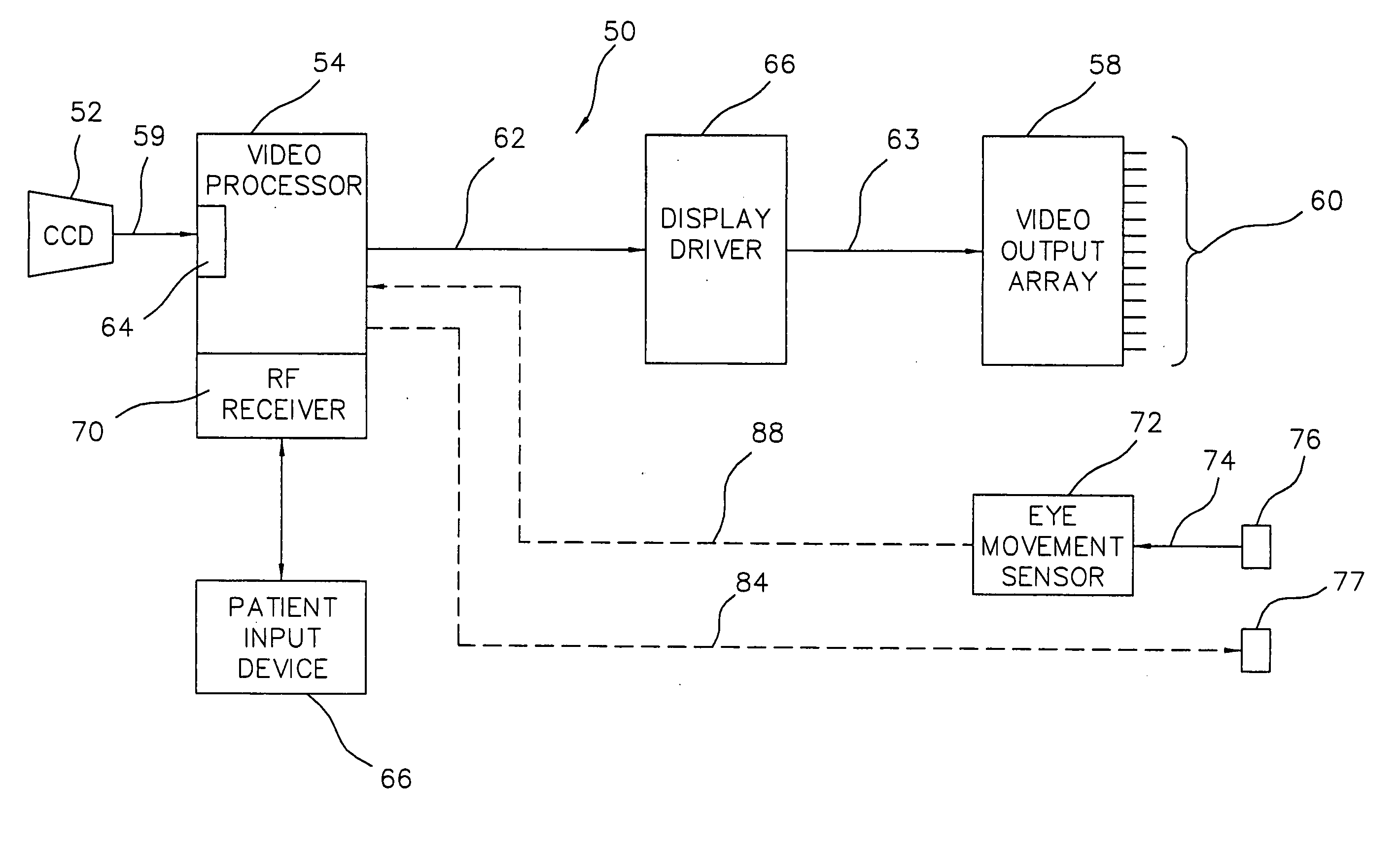
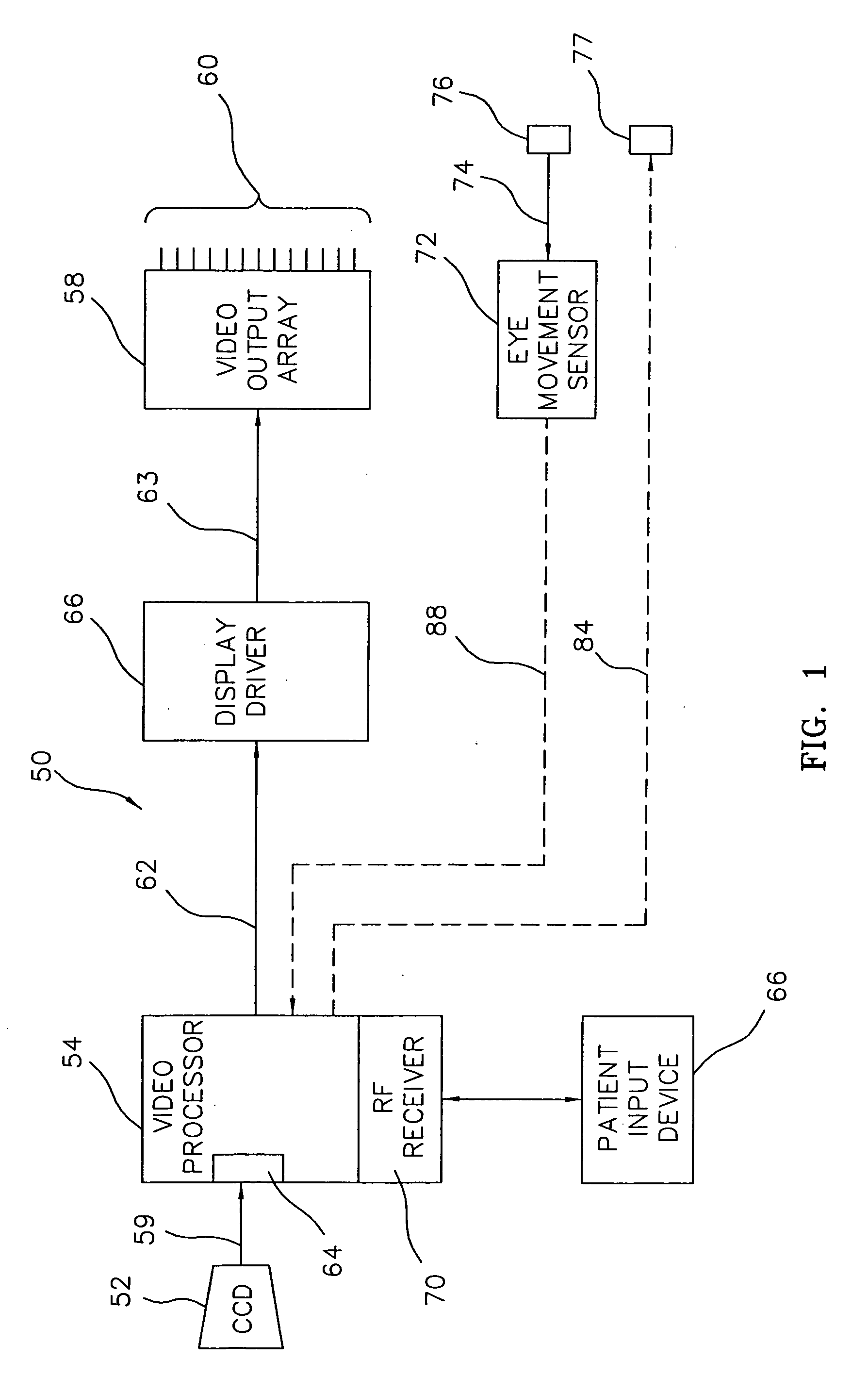
[0032] As shown in FIG. 1, an exemplary embodiment 50 of the present invention is primarily comprised of a (1) a “high” resolution video input device 52, (2) a video processor 54, (3) a display driver 56, and (4) a “low” resolution video output array 58. In a preferred embodiment, the “high” resolution input device 52, e.g., a CCD (charge coupled device) camera or equivalent, provides a video signal 59 that is typically of the order of 10,000-1,000,000 or more pixels of resolution. Also, in a preferred embodiment, the “low” resolution output array 58 is a retinal prosthesis comprised of an electrode array 60 that is capable of stimulating neural pathways, e.g., ganglion or bipolar cells at the patient's retina, and thus provides perceivable visual information, i.e., phosphenes, to the patient's brain. Typically, and for the foreseeable future, due to various mechanical, electromechanical, thermal and other technological limitations, the electrode array may be limited to be of the or...

case 1

[0122] Random Jittering [0123] a(t) and b(t) are random numbers determined from a random distribution with a definable or undefined distribution.

case 2

[0124] Preset scanning [0125] a(t) and b(t) have preset values that determine the rate and location of different pixel elements being summed for the ESP.


PUM


Abstract

A method and apparatus for improving visual acuity when providing a visual image from a “high” resolution input device to a “low” resolution output device. The described invention is of particular use when the output device is an array of electrodes as part of a retinal prosthesis used to restore vision to a visually-impaired patient. In that various limitations may, within the foreseeable future, limit the density of such an electrode array (and thus the resolution of the output image), the present invention teaches techniques to assign processed pixel subsets of a higher resolution image to a single electrode. By varying the pixel subsets, e.g., by jittering, and / or altering the processing criteria, the perceived visual acuity may be further improved. Alternatively and additionally, such processing may be further extended to drive neighboring electrodes in combination to thus stimulate virtual electrode sites and thus further enhance visual acuity.

Description

[0001] This application claims the benefit of U.S. Provisional Application No. 60 / 207,529 filed May 26, 2000.[0002] This invention was made with government support under grant No. R24EY12893-01, awarded by the National Institutes of Health. The government has certain rights in the invention.FIELD OF THE INVENTION [0003] The present invention is generally directed to visual, e.g., video, processing techniques and is of particular use in conjunction with an implantable medical device, e.g., a retinal prosthesis, for improving visual acuity. BACKGROUND OF THE INVENTION [0004] [°°°] Various conditions, e.g., age-related macular degeneration, retinitis pigmentosa, etc., exist which effect the functioning of photoreceptors (i.e., rods and cones) on a patient's retina and thus eliminate or severely degrade the patient's vision. To overcome these conditions, it has been proposed to directly stimulate the visual cortex (see for example, Bindley G, Lewin W. The sensations produced by electric...

Claims


Application Information

Patent Timeline
Patent Type & Authority Applications(United States)
IPC IPC(8): A61N1/05A61N1/36G06T3/40
CPCA61N1/36046G06T3/40
Inventor GREENBERG, ROBERT J.WILLIAMSON, RICHARD P.SCHULMAN, JOSEPH H.RASSOOL, REZA P.MANDELL, LEE J.SEIDMAN, ABRAHAM N.
Owner SECOND SIGHT MEDICAL PRODS
Learn More