
Remote monitoring system and method

a remote monitoring and monitoring system technology, applied in the field of remote monitoring systems and methods, can solve the problems of lack of user operability of the monitoring method in the above vehicle remote monitoring system, difficult application to a wide range of users, and difficulty in using, so as to enhance user convenience

Inactive Publication Date: 2005-12-08
DENSO CORP
View PDF13 Cites 41 Cited by
  • Summary
  • Abstract
  • Description
  • Claims
  • Application Information

AI Technical Summary

Benefits of technology

The present invention aims to enhance user convenience in a remote monitoring system and method for vehicles. The invention provides a system where a switch unit is associated with multiple pieces of vehicle information, and a user can obtain the necessary information by operating the switch unit. The vehicle information can include things like the vehicle's position, door open / closed state, window open / closed state, and interior image. The switch units can be displayed on a liquid crystal display screen or printed on paper. The system can be used in a vehicle manufacturing plant and the correspondence between the switch units and vehicle information can be set by the user. The communication terminal can include an operation device and a transceiver, and communications between them can be performed wirelessly or via a relay device. The relay device can automatically obtain and transmit vehicle information at a preset time. Overall, the invention provides a more convenient and user-friendly remote monitoring system for vehicles.

Problems solved by technology

Therefore, the monitor method in the above vehicle remote monitoring system lacks user's operability and is very difficult to use particularly to aged or other users unfamiliar with cellular phones.
The above system has been difficult for application to a wide range of users.

Method used


Image

  • Remote monitoring system and method
  • Remote monitoring system and method
  • Remote monitoring system and method

Examples


Embodiment Construction

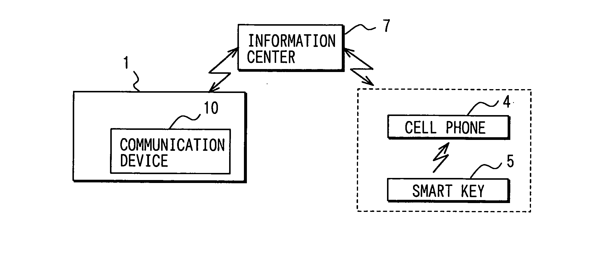
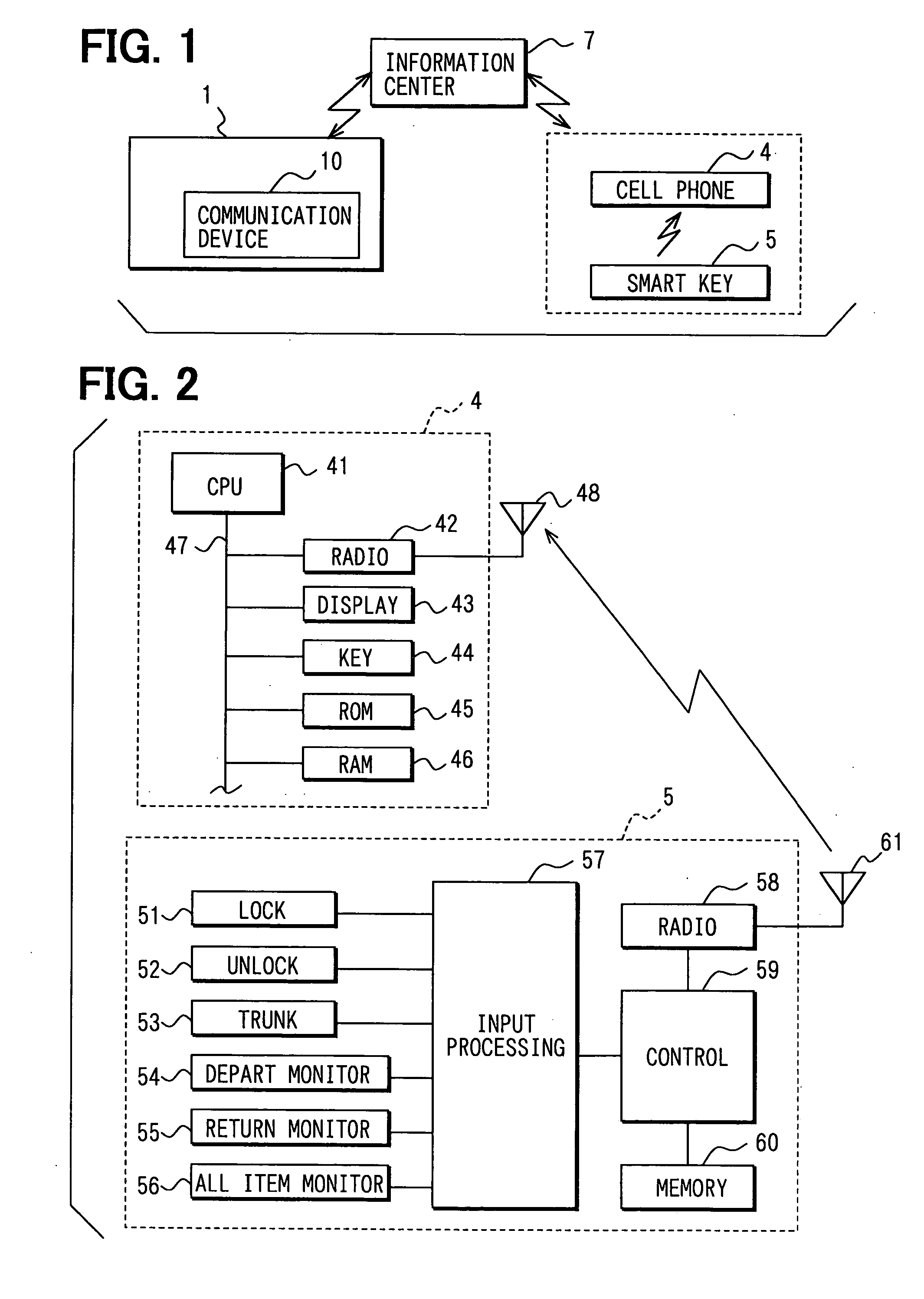
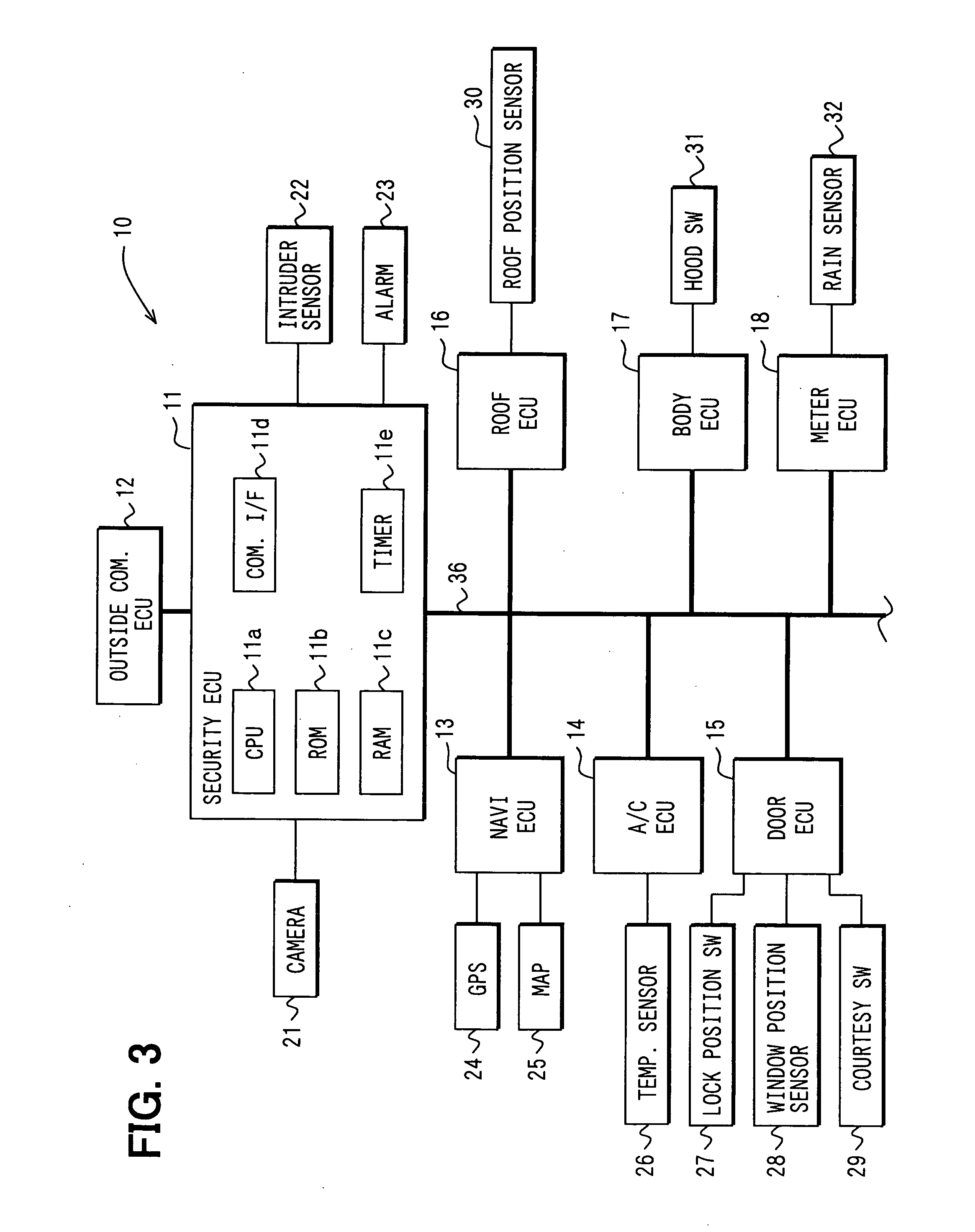
[0046] Referring to FIG. 1, a remote monitoring system is constructed as a remote security system, which includes a vehicle information communication device 10 mounted in a vehicle 1, a cellular phone 4, a smart key 5, and an information center (server) 7. The phone 4 and the key 5 are carried by a vehicle owner or user.

[0047] The cellular phone 4 is a known portable telephone. It has basic functions for voice conversation with other telephones over a telephone line, functions for transmitting and receiving electronic mail, a function for connecting to the Internet, and a Web browsing function. It further has a remote monitoring function that obtains and displays various pieces of information (monitor information) about states of the vehicle 1 and its surroundings by performing specified communications with the information center 7 upon receiving a specified operation signal from the smart key 5, or when the cellular phone 4 itself is operated. It also has a mail-based remote monit...


PUM


Abstract

A smart key carried with a user is provided with switches for monitoring a vehicle in remote places, such as a departure-time monitor switch, a return-time monitor switch and an all item monitor switch. The switches are associated with monitor information indicating various vehicle states. When the departure-time monitor switch is operated, the cellular phone receives monitor information such as parking position, rainfall state, etc. useful to the user at departure time from the vehicle. Similarly, when the return-time monitor switch is operated, the cellular phone receives monitor information useful at return time such as door open / closed state and lock state. When the all item monitor switch is operated, the cellular phone receives monitor information of all monitor items.

Description

CROSS REFERENCE TO RELATED APPLICATION [0001] This application is based on and incorporates herein by reference Japanese Patent Application No. 2004-168778 filed on Jun. 7, 2004. FIELD OF THE INVENTION [0002] The present invention relates to a remote monitoring system and method for monitoring a monitor object such as a vehicle by remote operations in remote places. BACKGROUND OF THE INVENTION [0003] In recent years, vehicles are required to enhance security performance for preventing vehicle theft and dragging. [0004] As a system for enhancing security performance, a vehicle remote monitoring system is proposed to monitor a present position and states of a vehicle, locks and unlocks doors, starts up an engine and performs other operations in remote places by using a cellular phone (e.g., a car communication system by use of portable mail function (i-mobisses), [online], updated: Apr. 16, 2004, Apex Communications Co., Ltd., (searched May 10, 2004), Internet<URL: http: / / www.apex-...

Claims


Application Information

Patent Timeline
Patent Type & Authority Applications(United States)
IPC IPC(8): E05B49/00B60R25/01B60R25/10B60R25/102B60R25/24B60R25/31B60R25/34G06F17/00G08B25/04G08B25/10
CPCB60R25/00B60R25/1012B60R25/2009B60R25/209B60R25/305B60R25/33B60R2325/205
Inventor KITAO, JUNICHISHIMONOMOTO, IFUSHISHIMOMURA, TOSHIO
Owner DENSO CORP
Learn More