Gold code generator design

a generator and gold technology, applied in the field of pseudonym generators, can solve the problems of difficulty in parallel implementation of gold code generators in arithmetic logic units or other computational units that operate on parallel data, and achieve the effect of reducing the range of output taps and being easy to implement parallel implementations

Inactive Publication Date: 2005-12-08
INTEL CORP
View PDF0 Cites 24 Cited by
  • Summary
  • Abstract
  • Description
  • Claims
  • Application Information

AI Technical Summary

Benefits of technology

[0009] Since the second output is in fact a delayed version of the first output, the gold code generator can be implemented by forming two pairs of linear feedback shift registers and using different seeds for the second pair of linear feedback shift registers. This significantly reduces the range of the output taps in any of the linear feedback shift registers, and makes it easier to implement a parallel implementation of the gold code generator to produce multiple output bits.

Problems solved by technology

This broad range of taps makes it difficult to implement a parallel implementation of the gold code generator in arithmetic logic units or other computational units that operate on parallel data.

Method used


Image

  • Gold code generator design
  • Gold code generator design
  • Gold code generator design

Examples


Embodiment Construction

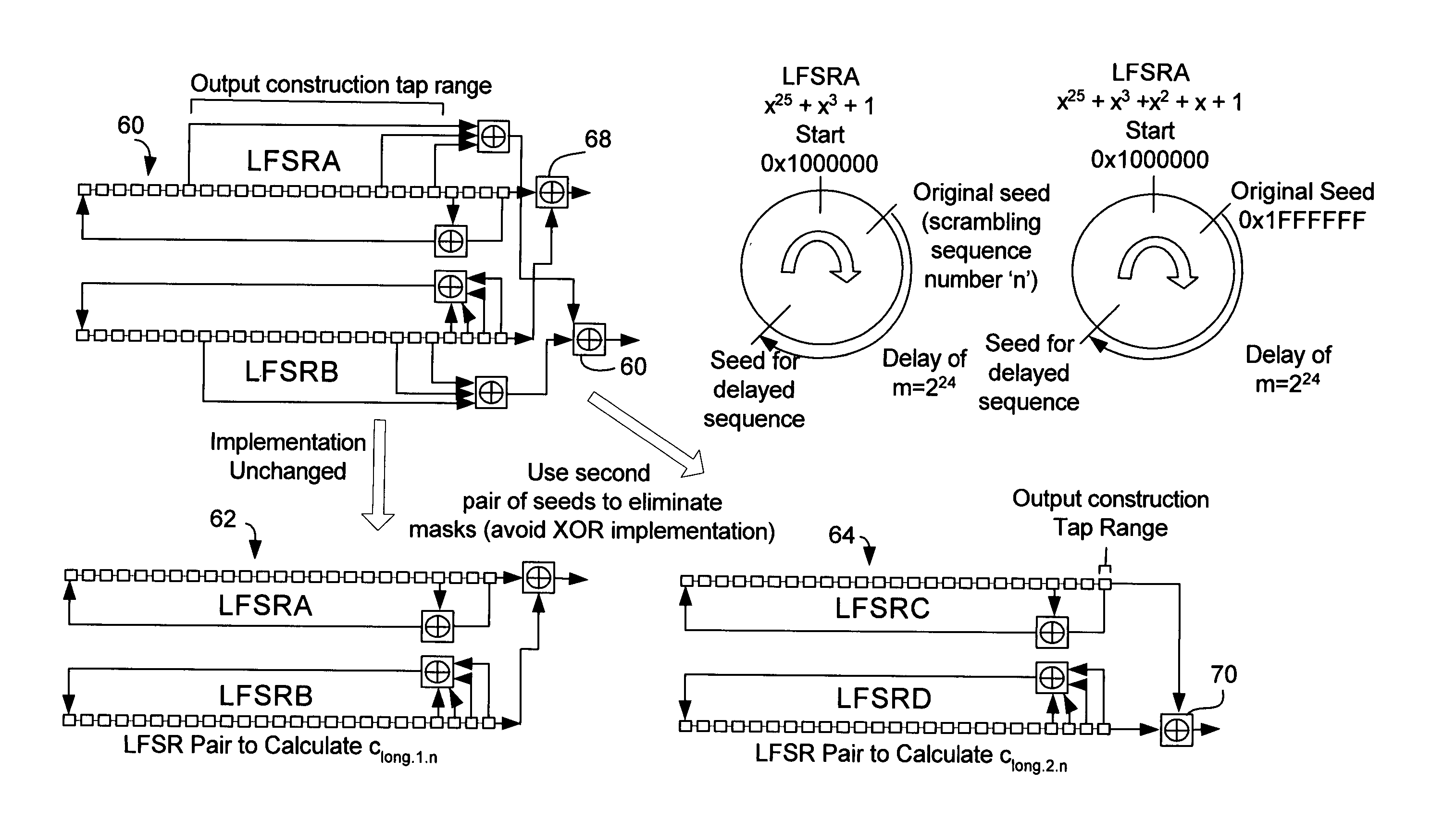
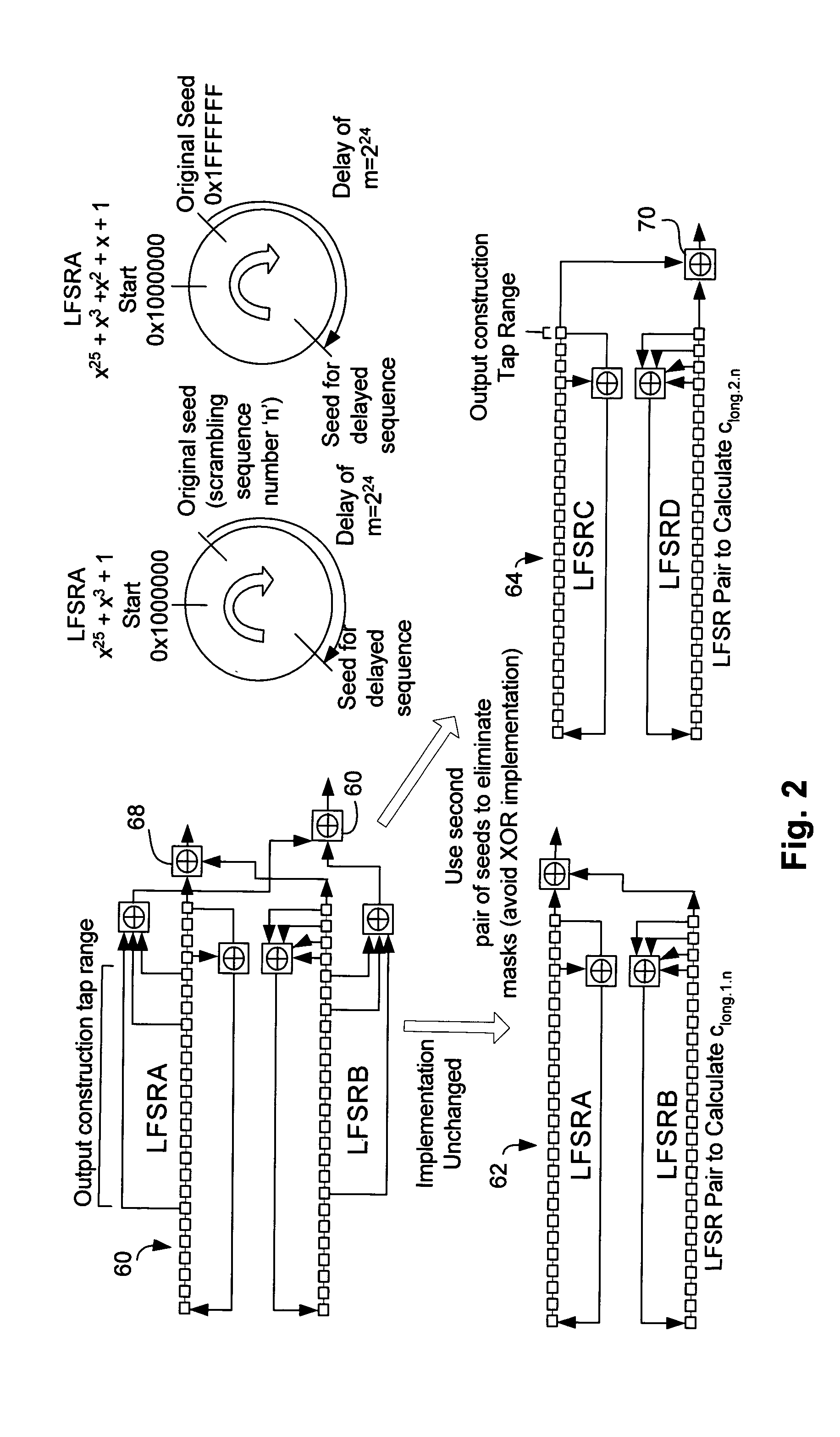
[0022]FIG. 2 illustrates the conversion of the gold code generator 60 as defined in the UMTS specification into an equivalent representation using two pairs of linear feedback shift registers, pairs 62 and 64. The output from unit 66 of the gold code generator 60 is equivalent to a delayed sequence of the output unit 68. In the present invention, multiple pairs of the linear feedback shift register are used, the second pair of linear feedback shift registers uses a second pair of seed values such that output of the second pair of linear feedback shift registers 64 is a delayed sequence of the sequence produced by the output 66 of the gold code generator 60.

[0023] Although the equivalent representation uses more resources, this equivalent representation can be implemented in a parallel implementation that produces multiple output bits. Such a representation is especially useful when implemented with a reconfigurable chip in which reconfigurable elements are configured by configurati...


PUM


Abstract

A gold code generator is described comprising two pairs of linear feedback shift registers, the seed values for the second pair of linear feedback shift registers are different from the seed values for the first pair of linear feedback shift registers. The second seed values are calculated from the first seed values. The use of this second pair of linear feedback shift registers prevents the need to use a wide span of taps to the linear feedback shift register to produce output bits. By using two pairs of linear feedback shift registers, a parallel output implementation can be produced in which multiple output bits are produced in a single clock cycle.

Description

BACKGROUND OF THE PRESENT INVENTION [0001] The present application concerns pseudo-random generators, in particular gold code generators. [0002] Pseudo-random generators have applicability for a number of communication systems, in particular, for spread spectrum wireless communications. In spread spectrum transmissions, the circuit artificially spreads the transmitted signals bandwidth by modulating an information signal, either in phase or frequency, with a pseudo-random sequence that occurs at a greater rate than that required for the data alone. During signal reception, the receiver synchronizes an internal pseudo-random generator to the pseudo-random sequence of the transmitted signal to fully recover the available power and decode the message. Most direct sequence spread spectrum systems pseudo-randomly modulate the phase of the RF carrier signal 10 times or greater than the rate required for the data transmission. This results in a signal spectrum which is much broader than wo...

Claims


Application Information

Patent Timeline
Patent Type & Authority Applications(United States)
IPC IPC(8): G06F1/02G06F7/58
CPCG06F7/584G06F2207/583
Inventor PUGH, DANIEL J.ROLLINS, MARK
Owner INTEL CORP
Why Eureka
Try Eureka