Analog signal processor, as well as, a data register rewriting method and a data transmission method thereof

a technology of analog signal processor and data register, which is applied in the direction of generating/distributing signals, instruments, micro-instruction address formation, etc., can solve the problems of long time, inability to obtain communication at high speed, and up to be a problem on the processing speed of the controller

Inactive Publication Date: 2005-12-08
HITACHI-LG DATA STORAGE
View PDF4 Cites 10 Cited by
  • Summary
  • Abstract
  • Description
  • Claims
  • Application Information

AI Technical Summary

Benefits of technology

[0043]FIG. 18 is a view for showing an example of “Read Modify Write” within the system relating to the conventional art mentioned above; and
[0044]FIG. 19 is a block diagram for showing an example of the system relating to the conventional art mentioned above.

Problems solved by technology

As was mentioned above, not only the transmission operation to the ASP, but also the receiving for reading the register, when conducting the “read modify write” process between the ASP and the controller through the serial communication, therefore, it takes a long time.
With this, it is impossible to obtain the communication at high speed, and also, for this reason, it comes up to be a problem on the processing speed of the controller.
However, since the communication module of the microcomputer cannot cope with the timing of such the specialized specification, therefore in general, it must be deal with a method; i.e., while transmitting the signals with using the serial communication module, and thereafter receiving the signals through software, by switching over the port setting.
However, regarding a certain part of the functions, and further the functions, which will be needed for the ASP in the future, there can be considered also a case of requiring such the accessing function at the high speed, as was mentioned, and in such the case, the speed of the serial communication comes to be a big problem.

Method used


Image

  • Analog signal processor, as well as, a data register rewriting method and a data transmission method thereof
  • Analog signal processor, as well as, a data register rewriting method and a data transmission method thereof
  • Analog signal processor, as well as, a data register rewriting method and a data transmission method thereof

Examples


second embodiment

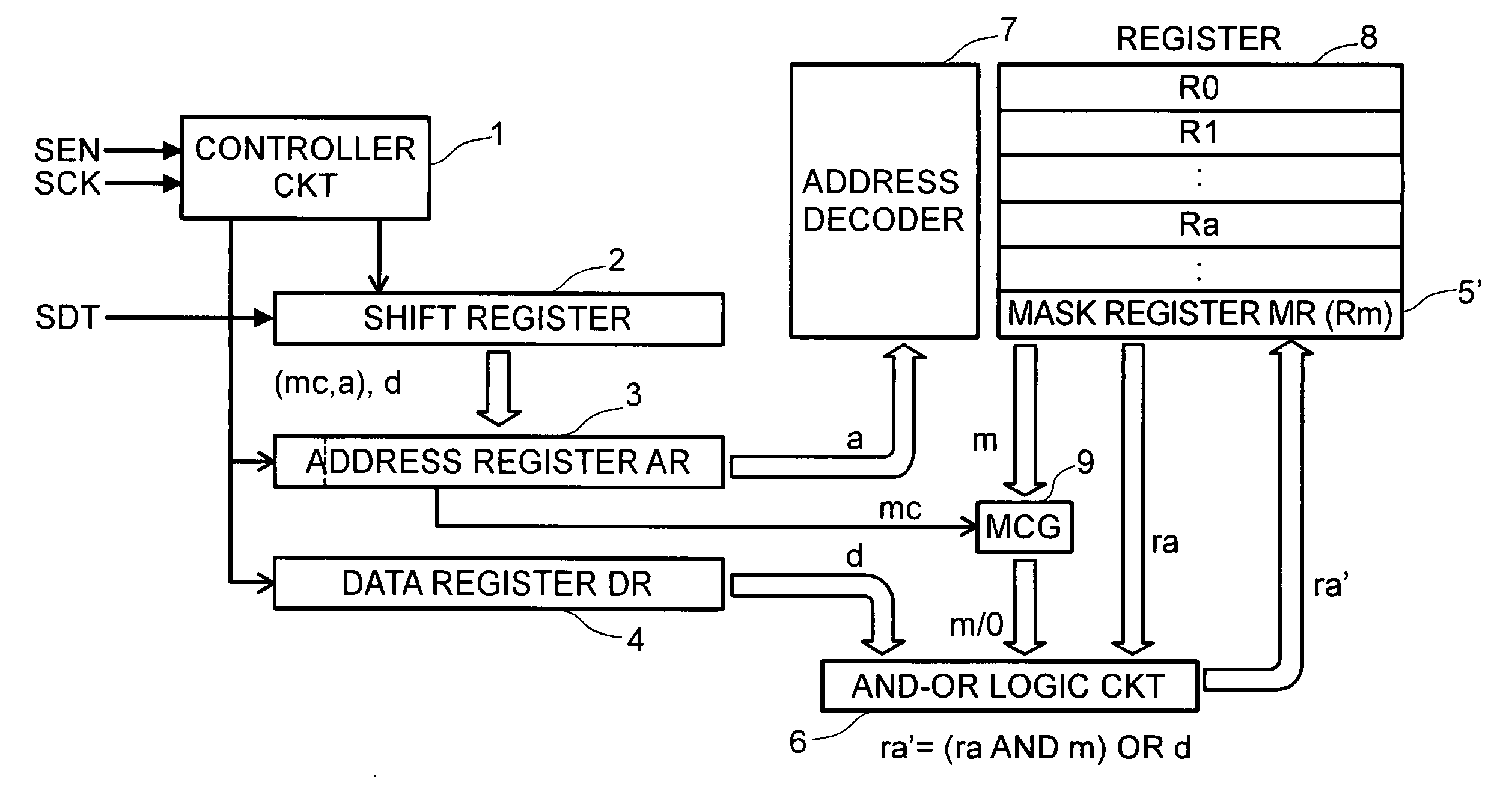
[0062] On the other hand, FIG. 9 shows the structure of the serial data to be transmitted from the system controller side into the analog signal processor, according to the As is apparent from the figure, the setting value data to be transmitted together with the enable signal “SEN” and the synchronous clock signal “SCK”, i.e., the serial data “SDT”; it is constructed by providing a bit “mc” for determining the mask control to be valid / invalid, at a head thereof, while disposing the address data “a” and the setting value data “d”, one by one, at a rear thereof, as is shown in the figure.

[0063] With the analog signal processor according to the second embodiment mentioned above, the mask control bit “mc” at the head of the address register 3 is inputted into a control terminal of the AND gate (MCG) 9 for use of mask controlling, while from the registers 8 is read out the predetermined mask data stored into the mask register (MR (Rm)) 5′, to be outputted into the AND-OR logic circuit ...

third embodiment

[0067] Also, FIG. 11 attached herewith shows the structure (i.e., the protocol) of the serial data to be transmitted from the system controller side to the analog signal processor according to the As is apparent from the figure, the setting value data to be transmitted together with the enable signal “SEN” and the synchronous clock signal “SCK”, being the so-called serial data signal “SDT”, it is provided with, for example, a mask selection data “mi” of two (2) bits, for indicating which mask data should be selected, at the head thereof, but it is constructed in the same to the mentioned above, i.e., disposing the address data “a” and the setting data “d” in rear thereof.

[0068] With such the analog signal processor according to the third embodiment, it is possible to cause the registers 8 to output the desired mask data into the AND-OR logic circuit portion 6, together with the data stored within the desired address, by means of the address data within the address register 3 and th...

fourth embodiment

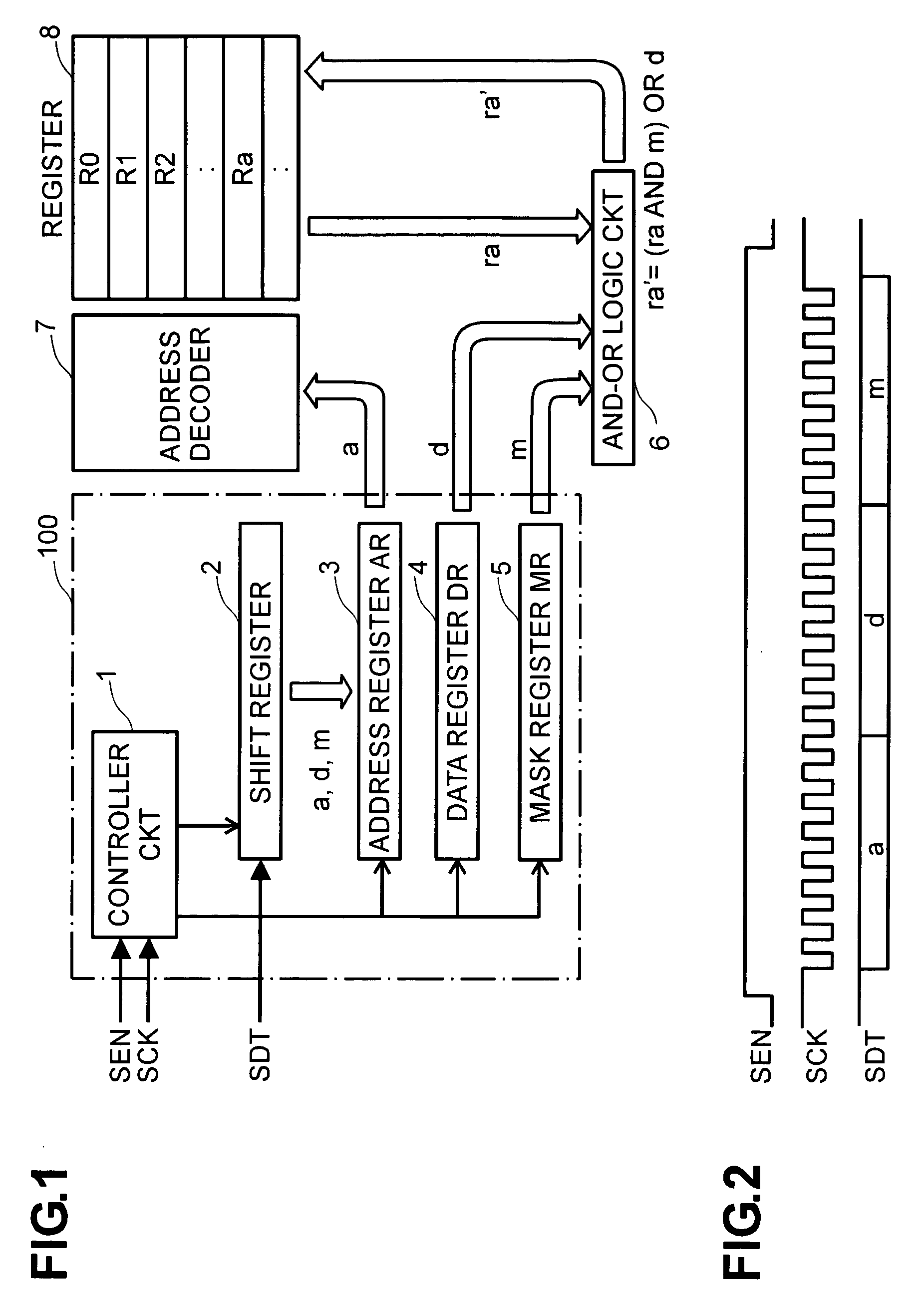
[0071] With the analog signal processor mentioned above, in the similar manner to the above, first the serial data “SDT” inputted together with the enable signal “SEN” and the synchronous clock signal “SCK” is held within the shift register 2, once, and then shifted into the address register 3, the data register 4, and the command bit pattern selection register 11, to be held therein, respectively, depending upon the control output of the controller circuit 1. And, it is almost same to that mentioned above, that the data “ra” of eight (8) bits, which is stored at the desired address within the registers 8, is read out therefrom, through the address decoder 7, in accordance with the address data “a” of eight (8) bits held in the address register 3, to be supplied into the arithmetic logical operation circuit or unit (ALU) 10, together with the setting data “d” held within the data register 4.

[0072] And, in this fourth embodiment, the data “c” at the upper three (3) bits (CR) within ...


PUM

PropertyMeasurementUnit
lengthaaaaaaaaaa
bit lengthaaaaaaaaaa
timeaaaaaaaaaa

Abstract

An analog signal processor, accessing to a setting register through serial communication, for achieving high speed of selective bit setting therein, comprising: an address register 3, a data register 4, a mask register 5, and a AND-OR logic circuit 6, wherein address data “a”, setting data “d” and mask data “m” are transmitted through serial communication. Reading out a register designated by the address data “a” and conducting AND operation on the mask data “m” for each bit thereof, and further conducting OR operation upon the setting data “d” for each bit thereof, a result obtained thereby is written back into a register 8 designated by the address data. When no mask data portion is transmitted, the same process is conducted, assuming that it is the mask data of all bits being zero.

Description

BACKGROUND OF THE INVENTION [0001] The present invention relates to, so-called, an analog signal processor (Analog Signal Processor: ASP), being controllable from a controller side, which is made up with, such as, a microcomputer or the like, for example, through accessing to a resister provided within an inside thereof, via a serial communication, thereby enabling various kinds of signal processing in an analog manner therein, and it also relates to a data register rewriting method, for rewriting of setting data to such the analog signal processor, and further to a data transmission method for it. [0002] Generally, the analog signal processor (ASP) is widely applied within various kinds of apparatuses, including, such as, an optical disk apparatus, for example, as being an LSI for use in analog signal processing, to be controlled by a microcomputer or the like, being a system controller, and for the purpose of conducting various kinds of analog signal processing therein. [0003] Nam...

Claims


Application Information

Patent Timeline
Patent Type & Authority Applications(United States)
IPC IPC(8): G11B20/02G06F3/06G06F13/38G06F12/00G06F1/04
CPCG06F3/0601G06F2003/0692G11B20/02G06F3/0673G06F1/04
Inventor TSUJIMURA, HIROFUMI
Owner HITACHI-LG DATA STORAGE
Why Eureka
Try Eureka