Evaporative emissions control system for small internal combustion engines

a technology of emission control system and internal combustion engine, which is applied in the direction of condensed fuel collection/return, charge feed system, non-fuel substance addition to fuel, etc., can solve the problem that fuel vapors may escape from the fuel supply system to the atmospher

Inactive Publication Date: 2005-12-15
CERTIFIED PARTS
View PDF67 Cites 23 Cited by
  • Summary
  • Abstract
  • Description
  • Claims
  • Application Information

AI Technical Summary

Benefits of technology

[0010] The present invention provides an evaporative emissions control system for small internal combustion engines. The system generally includes a charcoal canister and a carburetor with a fuel circuit shutoff valve. The charcoal canister is in fluid communication with the air space above the liquid fuel within the engine fuel tank, and optionally, with the air space above the liquid fuel within the fuel bowl of a fuel bowl-type carburetor. The charcoal canister contains charcoal media which absorbs fuel vapors when the engine is not running. During running of the engine, vacuum within

Problems solved by technology

A problem with the existing intake and fuel supply systems of such small internal combustion engines is that fuel v

Method used


Image

  • Evaporative emissions control system for small internal combustion engines
  • Evaporative emissions control system for small internal combustion engines
  • Evaporative emissions control system for small internal combustion engines

Examples


first embodiment

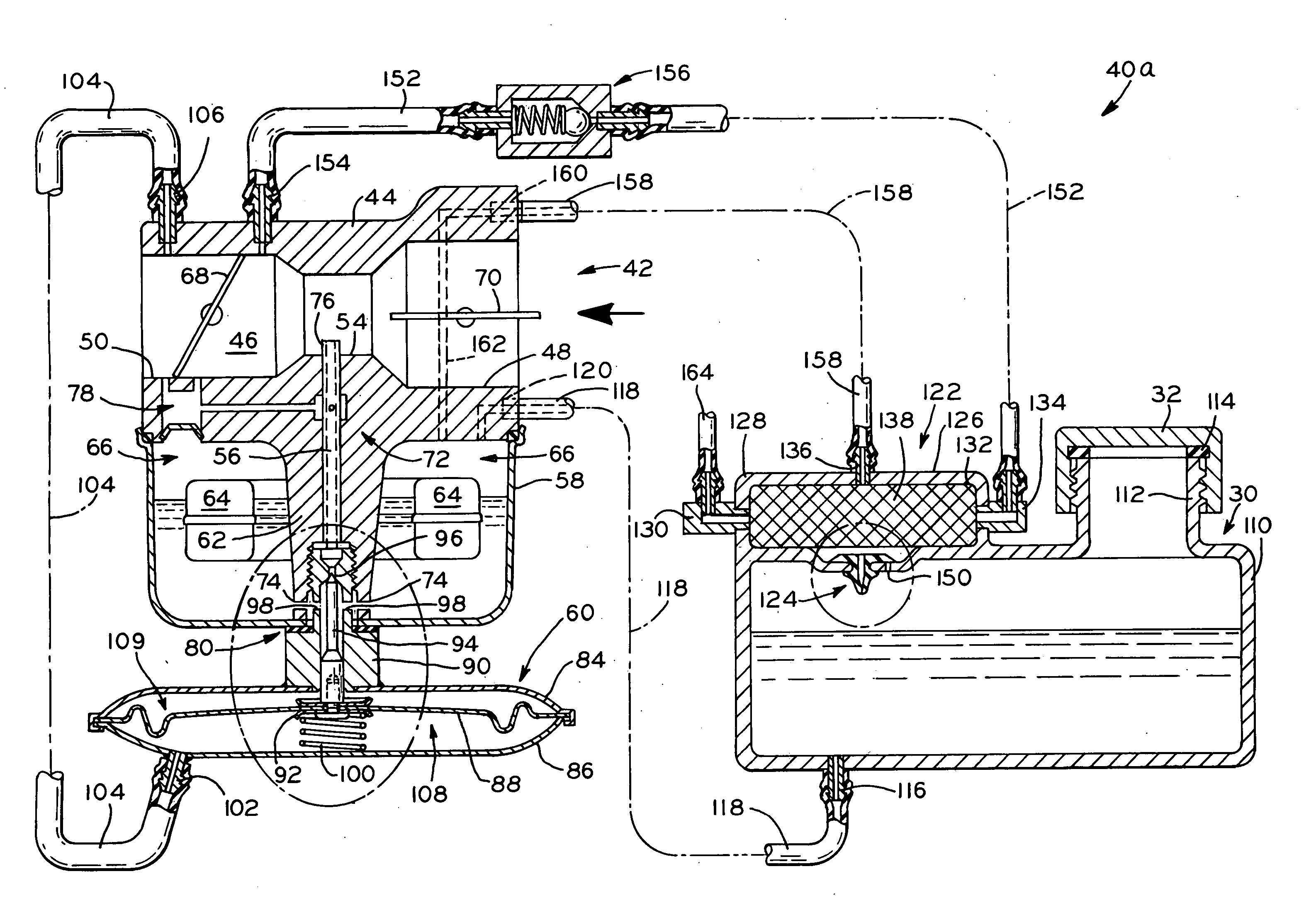
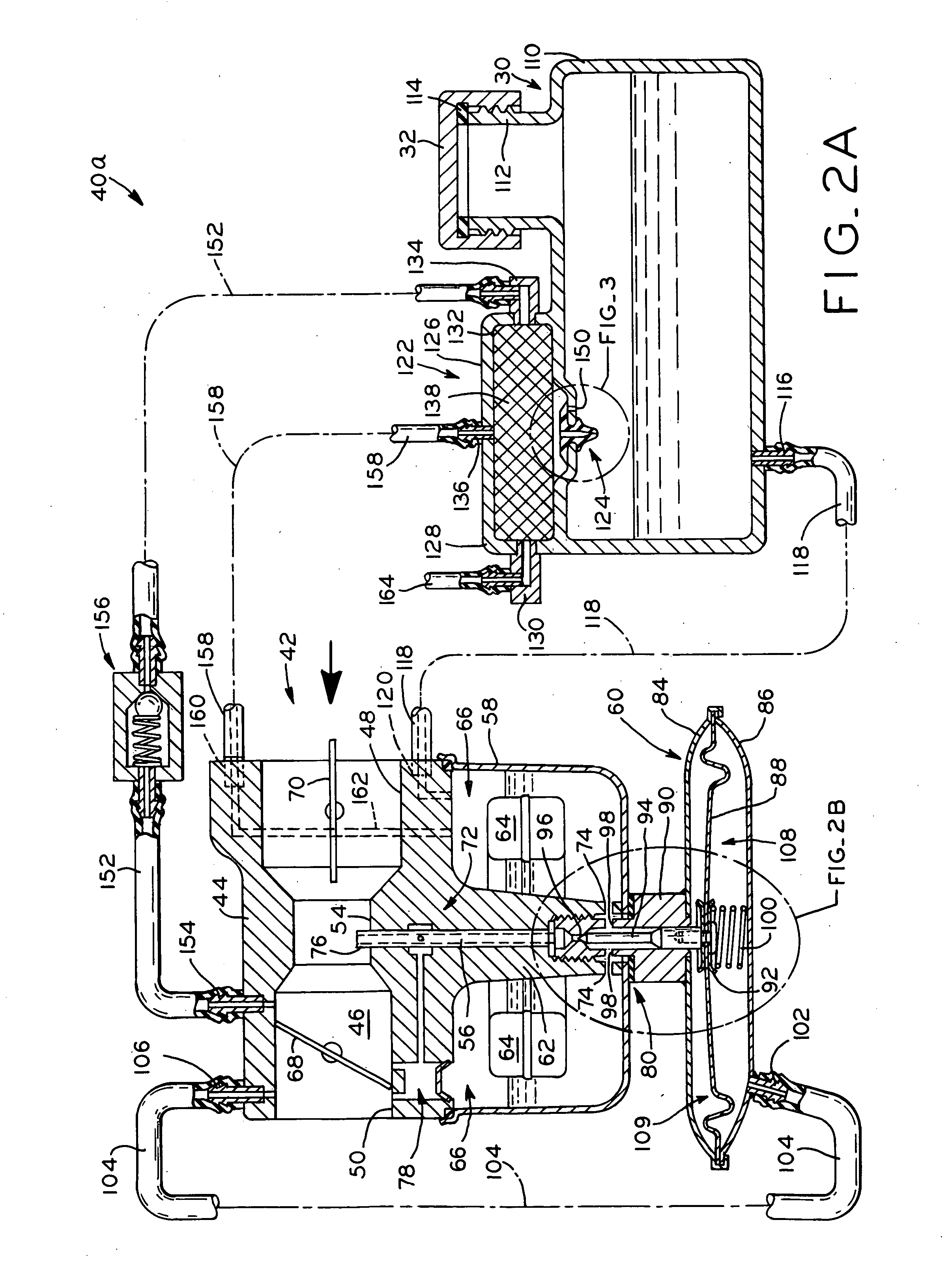
[0035] Referring to FIG. 2A, an evaporative emissions control system 40a in accordance with the present invention is shown, which includes a float bowl-type carburetor 42. Carburetor 42 generally includes carburetor body 44 having an air intake passage or throat 46 with inlet end 48 connected to an air filter (not shown), and outlet end 50 connected to the intake manifold 52 (FIG. 1) of engine 28. Throat 46 includes a constricted portion or venturi 54 proximate the nozzle of main fuel jet 56 through which liquid fuel is drawn from fuel bowl 58 of carburetor 42 into throat 46 for mixing with intake air in a known manner during running of engine 28. Fuel bowl 58 is connected to carburetor body 44 by valve housing 60 attached to stem portion 62 of carburetor 42 in the manner described below. Fuel bowl 58 contains a volume of liquid fuel therein, and includes an inlet valve (not shown) actuated by float 64 for metering liquid fuel into fuel bowl 58 in a known manner from fuel tank 30 vi...

second embodiment

[0052] Referring to FIG. 4A, evaporative emissions control system 40b according to the present invention is shown. Many of the components of evaporative emissions control system 40b, including fuel tank 30 and charcoal canister 122, for example, are identical to those of evaporative emissions control system 40a described above, and identical reference numerals have been used to denote identical elements therebetween.

[0053] Evaporative emissions control system 40b includes diaphragm carburetor 170, which generally includes carburetor body 172 having throat 174 with inlet end 176 connected to an air filter (not shown), and outlet end 178 connected to the intake manifold 52 (FIG. 1) of engine 28. Throat 174 includes a constricted portion or venturi 180 proximate the main fuel jet 192 through which liquid fuel is drawn into throat 174 for mixing with intake air in a known manner during running of engine 28. Carburetor 170 additionally includes throttle valve plate 182 downstream of vent...


PUM


Abstract

An evaporative emissions control system for small internal combustion engines. The system generally includes a charcoal canister and a carburetor with a fuel circuit shutoff valve. The charcoal canister is in fluid communication with the air space above the liquid fuel within the engine fuel tank, and optionally, with the air space above the liquid fuel within the fuel bowl of a fuel bowl-type carburetor. The charcoal canister contains charcoal media which absorbs fuel vapors when the engine is not running. During running of the engine, vacuum within the carburetor induces a flow of atmospheric air through the charcoal canister to purge the collected fuel vapors from the charcoal media, and the fuel vapors pass into the engine for consumption. The carburetor of the engine, which may be either a fuel bowl-type carburetor or a diaphragm carburetor, includes a fuel circuit shutoff valve controlled either by a vacuum signal produced within the engine or by a user-actuated mechanical linkage. The fuel circuit shutoff valve closes the fuel circuit of the carburetor upon engine shutdown to prevent escape of fuel vapors from the carburetor to the atmosphere. In another embodiment, a weir-type carburetor is disclosed which contains a minimal amount of fuel when the engine is not running to reduce or eliminate evaporative emissions.

Description

CROSS-REFERENCE TO RELATED APPLICATIONS [0001] This application claims the benefit under Title 35, U.S.C. §119(e) of U.S. Provisional Patent Application Ser. No. 60 / 579,530, entitled EVAPORATIVE EMISSIONS CONTROL SYSTEM FOR SMALL INTERNAL COMBUSTION ENGINES, filed on Jun. 14, 2004.BACKGROUND OF THE INVENTION [0002] 1. Field of the Invention [0003] The present invention relates to small internal combustion engines of the type used with lawnmowers, lawn tractors, and other utility implements. In particular, the present invention relates to an emissions control system for such engines. [0004] 2. Description of the Related Art [0005] Small internal combustion engines of the type used with lawnmowers, lawn tractors, and other small utility implements typically include an intake system including a carburetor attached to the engine which mixes liquid fuel with atmospheric air to form a fuel / air mixture which is drawn into the engine for combustion. [0006] One known type of carburetor inclu...

Claims


Application Information

Patent Timeline
IPC IPC(8): F02M25/08
CPCF02M25/0809F02M25/0836F02M25/0854F02M25/089
Inventor KIRK, J. DAVIDDONAHUE, RONALD J.CARPENTER, TODD L.
Owner CERTIFIED PARTS
Why Eureka
Try Eureka