Electronic control unit

a control unit and electronic technology, applied in the field of electronic control units, can solve the problems of inability to detect data destruction, and inability to carry out substation reporting without the request of the master station side, so as to reduce burden and improve control constant data quality

Inactive Publication Date: 2005-12-15
MITSUBISHI ELECTRIC CORP
View PDF4 Cites 20 Cited by
  • Summary
  • Abstract
  • Description
  • Claims
  • Application Information

AI Technical Summary

Benefits of technology

[0016] The present invention was made to solve the above-described problems, and has an object of providing an electronic control unit, which includes first and second control circuit sections electrically divided so as to mutually exchange serial signals, the electronic control unit being capable of improving a quality of a control constant data transmitted from the first control circuit section acting as a master station to the second control circuit section acting as a substation, and of reducing a burden required for communication control of a microprocessor on the master station side.
[0022] Furthermore, when there are much downstream communication of various set information from the first control circuit section acting as the master station to the second control circuit section acting as the substation at the start of operation, it is possible to diminish communication control burden on the master station side by making the regular report unavailable.

Problems solved by technology

A problem exists in that the presence or absence of data destruction can be detected only by individually reading out and checking control constants once a number of control constants have sequentially been received and stored in the constant setting register.
Moreover, any spontaneous upstream communication packet from the substation side (integrated circuit side) to the master station side (microprocessor side) is not prepared, and reporting from the substation side cannot be carried out without the request from the master station side.
Thus, regular requests become necessary in the case where there are regular report data, resulting in a problem that a useless downstream communication takes place.
In the above-mentioned on-vehicle electronic control unit disclosed in the Japanese Patent No. 3346163, a problem exists in the jam-up occurrence of downstream communication due to the fact control constants are transmitted on a regular basis during the operation in the case where there are a number of control constants having to be transmitted to the substation.
Even in the case where control constants are transmitted only at the start of operation and retransmitted during the operation only when a RAM data on the substation side and a ROM data on the master station side is in no coincidence as a result of comparison, a problem exists in that upstream communication is jammed up resulted from the transmission of comparison data to the master station in the case of carrying out the comparison on the master station side; and downstream communication for retransmitting a comparison data is jammed up in the case of carrying out the comparison on the substation side.
A problem exists in that the presence or absence of data destruction can be detected only by individually reading out and checking control constants once a number of control constants have sequentially been received and stored in the constant setting register.
Further, in the above-mentioned communication monitoring system disclosed in the Japanese Patent Publication (unexamined) No. 162814 / 1997, a problem exists in that a response delay takes place in detecting an error occurrence after the normal communication has continuously been carried out on condition that a threshold for communication error determination is set to be large.
On the contrary, a problem exists in that too sensitive error detection is carried out also in the case of trifle and sporadic error occurrence on condition that a threshold for error determination is set to be small.
Moreover, responses to a variety of communication errors of various types, and processing in the case of timeout error or the retransmission processing are not comprehensively described.

Method used


Image

  • Electronic control unit
  • Electronic control unit
  • Electronic control unit

Examples


embodiment 1

[0038] Hereinafter, referring to the drawings, a preferred embodiment according to the present invention is described.

[0039] In the drawings, like reference numerals indicate the same or like parts.

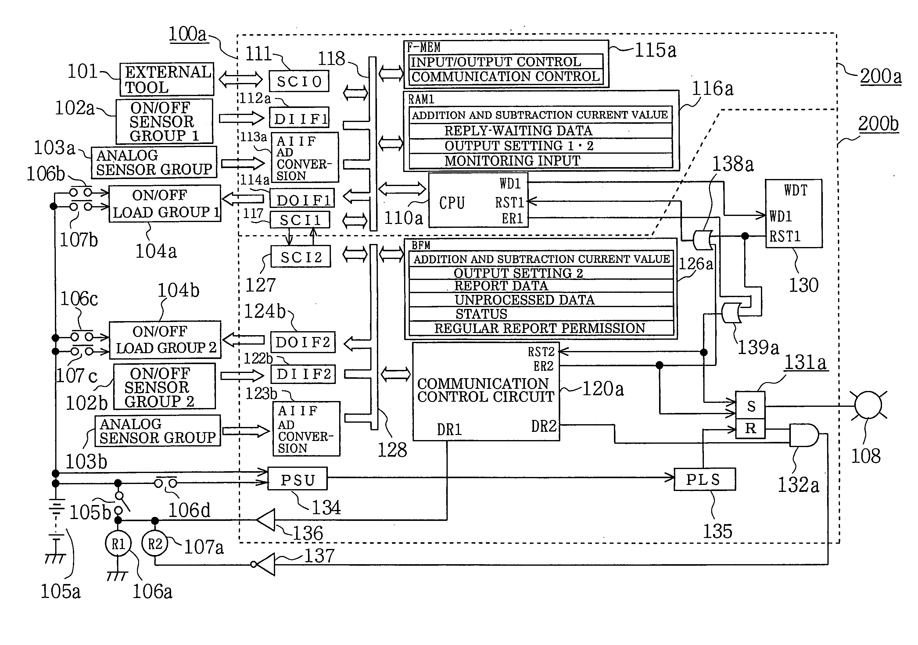
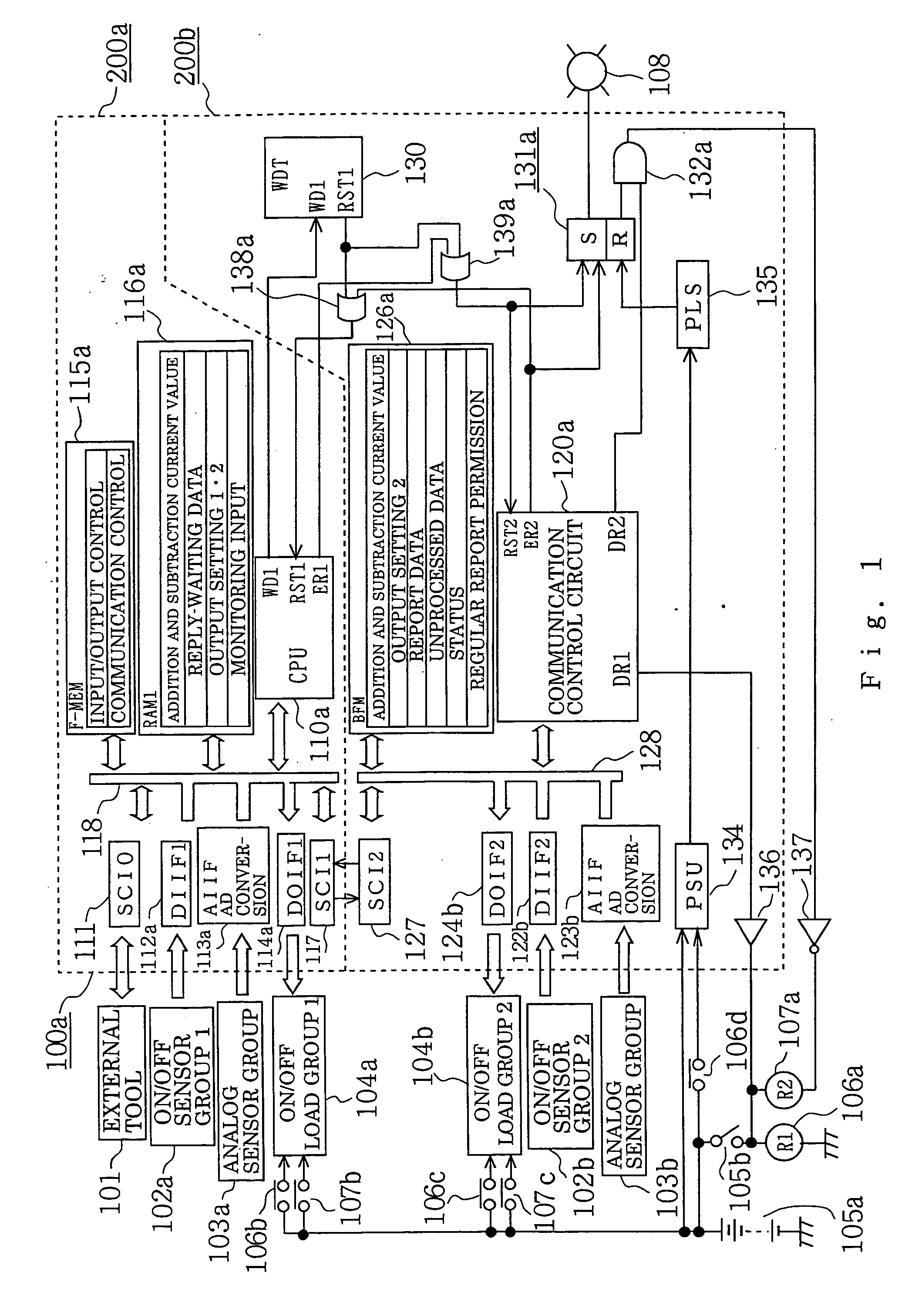
[0040] As shown in the drawings, an electronic control unit 100a according to a first embodiment consists of a first control circuit section 200a and a second control circuit section 200b.

[0041] First, external devices to be connected to the outside of the electronic control unit 100a are described.

[0042] An external tool 101 is connected via a detachable connector not shown, to the electronic control unit 100a at the time of product shipping or maintenance inspection, and functions to transfer and write a control program or a constant set data acting as a control constant in a later-described non-volatile program memory 115a.

[0043] A first input sensor group 102a serves as a sensor group, which performs an ON / OFF operation of relatively high speed and high frequency, and in which si...

embodiment 2

[0218]FIG. 8 is a block diagram showing the entire constitution of an electronic control unit according to a second preferred embodiment of the invention.

[0219] Major points of difference between the electronic control unit according to the foregoing first embodiment shown in FIG. 1 and the electronic control unit according to this second embodiment shown in FIG. 8 are as follows. In the electronic control unit according to the foregoing first embodiment of FIG. 1, the associative control circuit section (communication control circuit section) 120a is formed of integrated circuit elements employing a logical circuit. Whereas, in the electronic control unit according to this second embodiment of FIG. 8, an auxiliary CPU 120b is provided, and irregular transmission means is added to the first control circuit section.

[0220] Referring now to FIG. 8, constitution of the electronic control unit 100b according to the second embodiment is described.

[0221] The electronic control unit 100b...


PUM


Abstract

In an electronic control unit, a control constant stored in a program memory is transmitted to a data memory via a serial communication circuit. First control circuit section (master station) and second control circuit section (substation) mutually communicate through series-parallel converters. The master station includes regular transmission device and storage constant confirmation processing device. The substation includes regular report device and confirmation reply device to a data transmitted from the master station. A constant set data transmitted from the master station by regular transmission device is stored in the data memory at the time of normal receiving. Confirmation information such as sum value of the entire data in the data memory is reported by regular report device. At the master station, if there is any error in the confirmation information, a constant set data is retransmitted with regular transmission device. Reliability of data in the data memory is improved.

Description

BACKGROUND OF THE INVENTION [0001] 1. Field of the Invention [0002] The present invention relates to an electronic control unit containing therein a microprocessor for use in, e.g., fuel supply control of an automobile engine and, more particularly, to an on-vehicle electronic control unit improved in reliability of a control constant to be transmitted from a non-volatile program memory that is provided in a first control circuit section acting as a master station to a data memory that is provided in a second control circuit section acting as a substation in an electronic control unit including a plurality of control circuit sections electrically divided so as to exchange serial signals with each other. [0003] 2. Description of the Related Art [0004] An electronic control unit arranged to exchange information by the method of serial communication between a plurality of control circuit sections sharing functions therebetween, as well as to detect communication error and perform error...

Claims


Application Information

Patent Timeline
Patent Type & Authority Applications(United States)
IPC IPC(8): G06F13/38H04L12/40G11C16/06
CPCG06F13/385
Inventor TSUNEKAZU, SHOSOHASHIMOTO, KOHJIIWAGAMI, YUKIISHII, AKIHIRO
Owner MITSUBISHI ELECTRIC CORP
Why Eureka
Try Eureka