
Code quantity control apparatus, code quantity control method and picture information transformation method

a quantity control and code technology, applied in the field of code quantity control apparatus, can solve the problems of inability to calculate activity, inability to determine the length of a gop, and the circuit scale becomes inevitably large, so as to reduce the code quantity, improve the subjective picture quality, and improve the picture quality

Inactive Publication Date: 2005-12-15
SONY CORP
View PDF4 Cites 10 Cited by
  • Summary
  • Abstract
  • Description
  • Claims
  • Application Information

AI Technical Summary

Benefits of technology

The present invention provides a code quantity control apparatus, method, picture information transformation apparatus, and picture information transformation method for controlling the quantity of code in picture compressed information. The apparatus and method use information extracted from the picture compressed information to compute an optimum value for a reference quantization scale and keep it constant throughout the frame, resulting in output picture compressed information that avoids block distortion and has a smaller code quantity. The picture information transformation method also allows for computing an optimum value for the reference quantization scale and keeping it constant throughout the frame. Overall, the invention provides a more efficient and effective means for controlling the code quantity in picture compressed information.

Problems solved by technology

However, the amount of picture information in high resolution pictures is very large so that, picture information is compressed by adopting an encoding compression system such as the MPEG system or the like, there is raised a problem that a code quantity of about 18 to 22 Mbps or even greater is required for a case in which the picture frame is a jump-scanned picture with a frequency of 30 Hz and a resolution of 1,920×1,080 pixels in order to obtain a sufficiently high picture quality.
In this case, however, the circuit scale becomes inevitably large even though the deterioration of the picture quality can be avoided.
If this method is adopted in the picture information transformation apparatus 100 like the one shown in FIG. 11 as it is, however, two problems will arise.
In addition, the length of a GOP is not necessarily fixed.
Thus, since it is impossible to know luminance signal pixel values of the original picture, an activity cannot be calculated.
However, the amount of distortion caused by the coarse quantization process is not reduced by the finer re-quantization process.
In addition, since more bits are allocated to this macroblock, the number of bits allocated to the other macroblock must be reduced, causing the picture quality to further deteriorate.
Since the picture actually varies from frame to frame, however, the reference quantization scale Qj also varies over the screen, causing block distortion.
In dependence on the picture and the code quantity, however, the value of 10 may not necessarily be appropriate, causing the picture quality to deteriorate in some cases.

Method used


Image

  • Code quantity control apparatus, code quantity control method and picture information transformation method
  • Code quantity control apparatus, code quantity control method and picture information transformation method
  • Code quantity control apparatus, code quantity control method and picture information transformation method

Examples


Embodiment Construction

[0072] Some preferred embodiments of the present invention are described by referring to some of the diagrams.

[0073] A picture information transformation apparatus implemented by an embodiment of the present invention is characterized in that the picture information transformation apparatus has an information buffer and a code quantity control unit. The following description begins with an explanation of the picture information transformation apparatus that has an information buffer and a code quantity control unit as configuration elements.

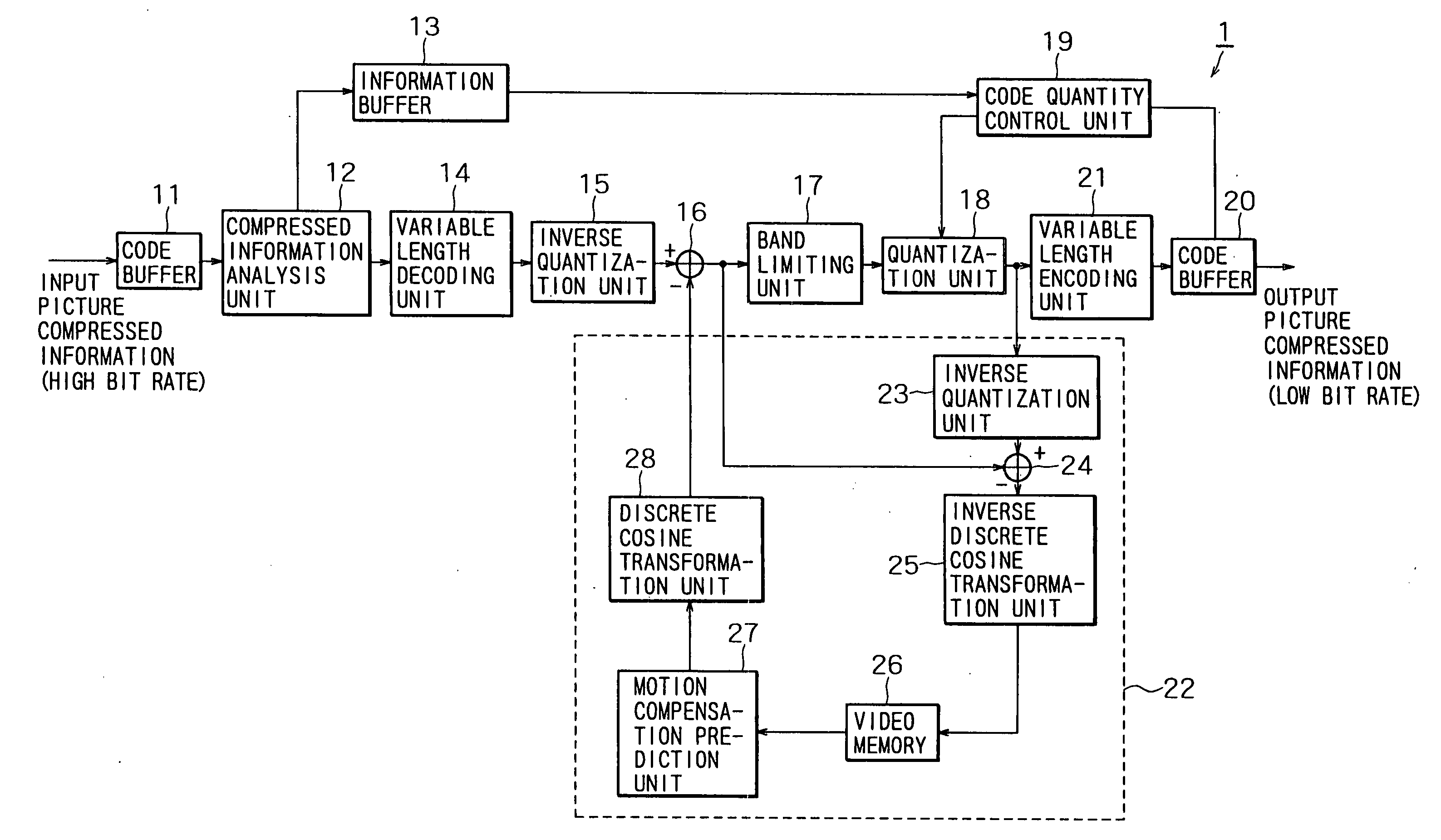
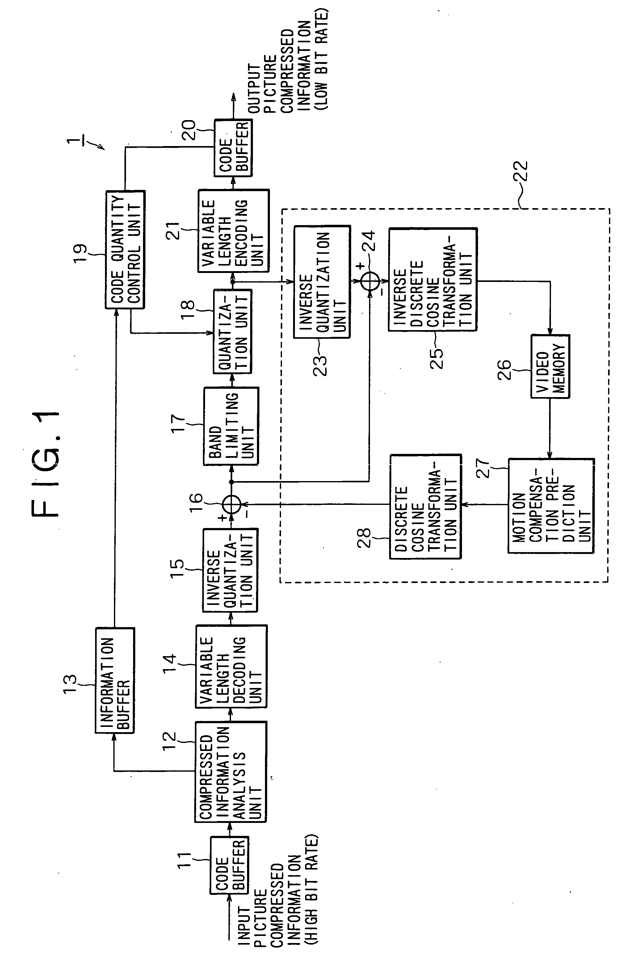
[0074]FIG. 1 is a diagram showing the configuration of a picture information transformation apparatus 1 wherein pixel data is transferred from a decoding unit employed in the apparatus 1 to an encoding unit also employed in the apparatus 1 through a frequency domain. As shown in the figure, the picture information transformation apparatus 1 includes a code buffer 11, a compressed information analysis unit 12, an information buffer 13, a variabl...


PUM


Abstract

Code quantity control based on a virtual buffer is executed by using information extracted from picture compressed information conforming to a predetermined system. Thus, a reference quantization scale can be held at a fixed value throughout a frame. As a result, it is possible to generate picture compressed information having a smaller code quantity.

Description

RELATED APPLICATION [0001] This application is a divisional application of application Ser. No. 10 / 035,240, filed on Jan. 4, 2002 the entire content being incorporated by reference.[0002] The present application claims foreign priority from Japanese Patent Application No. 2001-001803 filed on Jan. 9, 2001. The entirety of this application, including the specification, claims, drawings and summary, is incorporated herein by reference. BACKGROUND OF THE INVENTION [0003] The present invention relates to a code quantity control apparatus, a code quantity control method and so on, which are used in reception of picture information transmitted by way of a transmission means such as a satellite broadcasting system, a cable TV system or a network such as the Internet or used in the processing of picture information on a storage medium, such as an optical or magnetic disk, wherein the information has been compressed by orthogonal transformation, such as discrete cosine transformation, and by...

Claims


Application Information

Patent Timeline
Patent Type & Authority Applications(United States)
IPC IPC(8): H03M7/36H04N19/50H04N19/115H04N19/126H04N19/14H04N19/146H04N19/176H04N19/186H04N19/196H04N19/40H04N19/42H04N19/423H04N19/503H04N19/577H04N19/593H04N19/60H04N19/61H04N19/625H04N19/86H04N19/91
CPCH04N19/159H04N19/176H04N19/149H04N19/115H04N19/61H04N19/177H04N19/14H04N19/152H04N19/154H04N19/18H04N19/126
Inventor SATO, KAZUSHI
Owner SONY CORP
Learn More