Dual-source optical wavelength processor

a processor and optical wavelength technology, applied in the field of optical switches, can solve the problems of increasing the bandwidth of fibre optic communication fibres, increasing the demand for network functionality, and high loss

Active Publication Date: 2005-12-15
II VI DELAWARE INC
View PDF2 Cites 77 Cited by
  • Summary
  • Abstract
  • Description
  • Claims
  • Application Information

AI Technical Summary

Benefits of technology

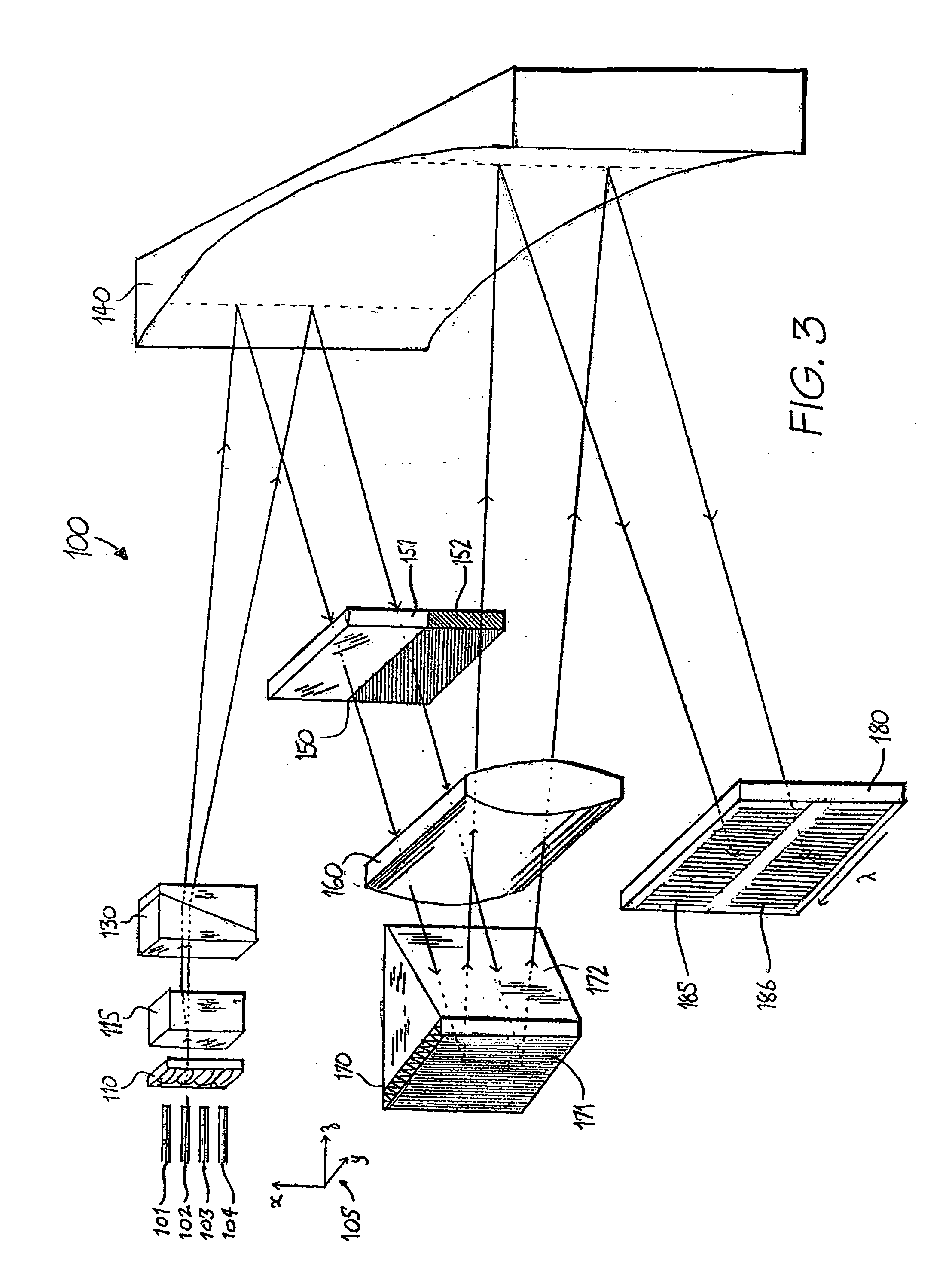
[0043] In accordance with a further aspect of the present invention, there is provided an optical signal manipulation system including: a series of optical signal ports; numerical aperture modifying means for modifying the numerical aperture of light emitted from the optical signal ports to form modified optical signals; polarisation manipulation means for imparting a different angular projection to substantially orthogonal polarisation states of the modified optical signals; polarisation alignment means for substantially aligning the polarisation state of the substantially orthogonal polarisation states; wavelength dispersion element for angularly dispersing by wavelength the aligned modified optical signals; a wavelength control element having a series of elongated control zones for receipt and manipulation of a region of the wavelength dispersed optical signals.
[0044] The different substantially orthogonal polarisation states are preferably manipulated by different elongated control zones. A first polarisation state can be manipulated by a first series of substantially adjacent control zones and a second orthogonal polarisation state can be manipulated by a second series of substantially adjacent control zones. The first and second series of substantially adjacent control zones are preferably substantially parallel with one another. Light from the wavelength control element can be projecting through a second wavelength dispersion element so as to combine wavelengths of the first and second series; Light from the second wavelength dispersion element can be projected through a second polarisation manipulation element for combining the orthogonal polarisations to output at predetermined optical signal ports. Light projected from the optical signal ports to the wavelength control element can undergo at least two reflections on reflective optical power surfaces.
[0045] The wavelength dispersion element preferably can include a diffraction grating mounted on an optical prism. Light from the polarisation manipulation means and light from the wavelength control el

Problems solved by technology

The increased bandwidth of fibre optic communication fibres is still often insufficient to cope with this demand without utilising the ability of these fibres to carry large numbers of individual communication channels each identified by the particular wavelength of the light.
The disadvantage of this technique is that the increasing density of wavelength channels places increasing demand on network functionality for connecting the individual channels to individual destination points on a dynamic basis, and for the ability to add or drop an individual wavelength channel into or out of the optical signal.
This is an optical power intensive architecture, which can provide for channel equalization and reconfiguration of wavelength selectivity, but is not scalable to multiple ports, has very high loss and because of the many auxiliary components such as wavelength tuneable filters has a large power and footprint requirement.
ii) Wavelength switches have been proposed for OADMs, but do not naturally provide for channel equalization, the channel by channel switching in general leads to dispersion and loss narrowing of optical channels, and in the case of multiple port switches it is generally not possible to switch between ports without causing impairment (a hit) on intermediate ports.
In addition the channel spacing cannot be dynamically reconfigured.
Tuneable 3-port filters have also been proposed having a lack of impairment to the express paths but do not scale easily to multiple ports and may suffer from transient wavelength hits during tuning.
In addition poor isolation of tunable 3 ports means they are less applicable to many add/drop applications which demand high through path isolation.
Usually two arrays of these mirrors are required to couple the light efficiently and because of the high degree of analogue control required structures based on this technology have proved to be extremely difficult to realize in practice and there are few examples of commerci

Method used


Image

  • Dual-source optical wavelength processor
  • Dual-source optical wavelength processor
  • Dual-source optical wavelength processor

Examples


Embodiment Construction

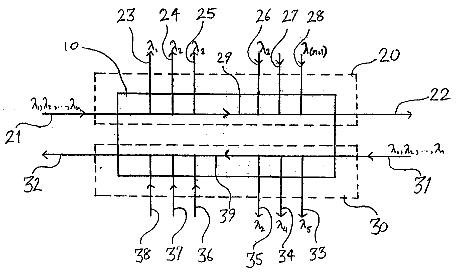
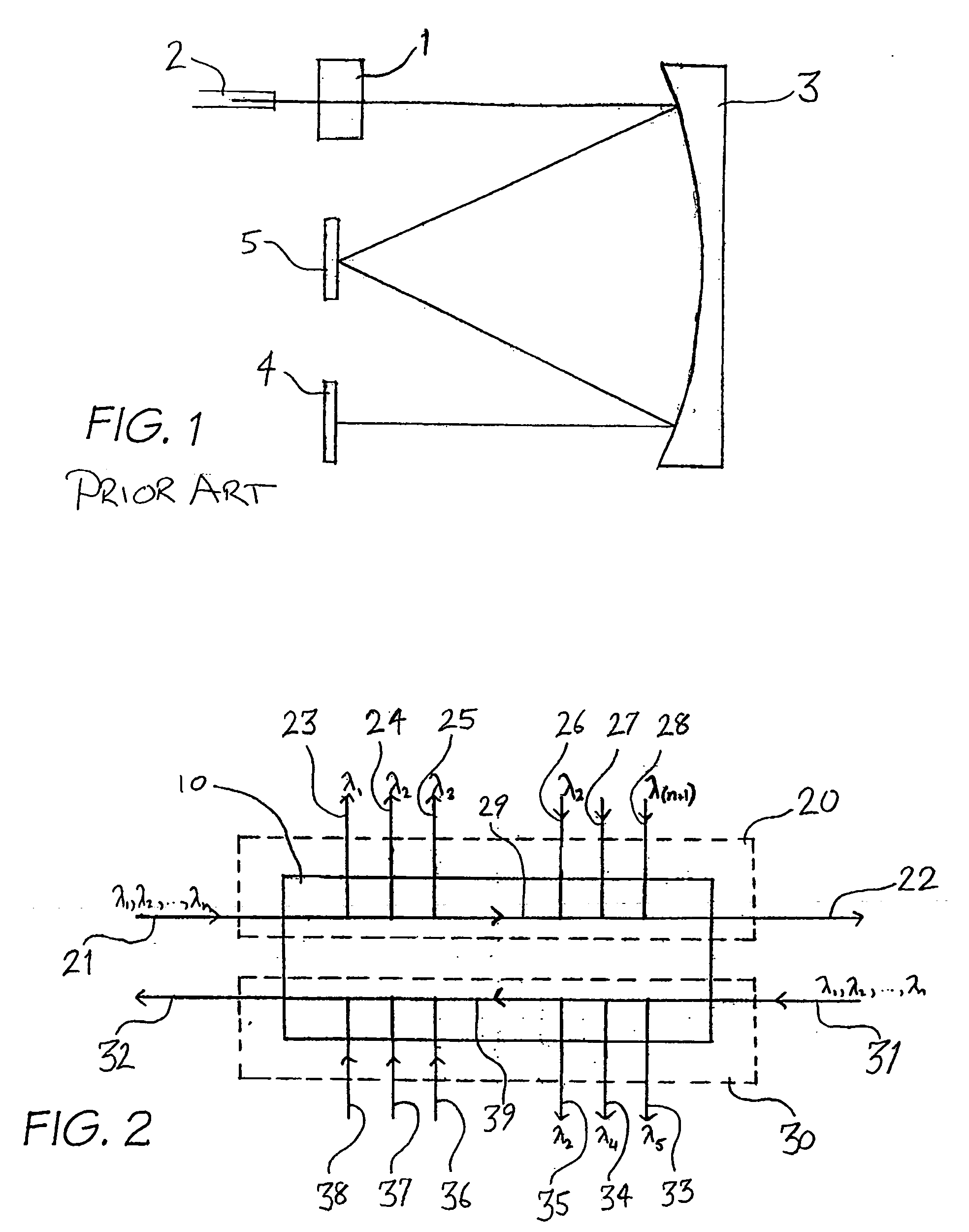
[0089] The preferred embodiment provides an optical switching device that can operate on individual spatially dispersed wavelength channels contained in an optical signal that originate from either of two input sources. The input sources can be: [0090] a) two unrelated sources possibly delivered to the switch via optical fibre; [0091] b) two orthogonally polarised beams originating from a single source, possibly delivered to the switch via optical fibre; [0092] c) a plurality of input sources, possibly delivered to the switch via optical fibre, separated into orthogonal polarisation states such that the polarisation states of a particular wavelength channel can be acted upon independently; [0093] d) a plurality of input sources, possibly delivered to the switch via optical fibre, optically tagged in a fashion that defines two distinct groups, for example by assigning each of the input sources one of two orthogonal polarisation states.

[0094]FIG. 2 shows a schematic block diagram of ...


PUM


Abstract

An optical signal manipulation system including: a series of ports for carrying a series of optical signals to be manipulated; a spatial separating means for spatially separating at least a first and a second group of light from the series of optical signals; wavelength dispersion element subsequently spatially separating wavelengths of the first and second series; wavelength processing means for processing separated wavelengths of the first and second series.

Description

FIELD OF THE INVENTION [0001] The present invention relates generally to optical switches, and in particular to a reconfigurable fibre optic wavelength switch that can operate independently on individual wavelength channels contained in optical signals originating from either of two input sources. BACKGROUND OF THE INVENTION [0002] The recent growth in the demand for broadband services has resulted in a pressing need for increased capacity on existing communication channels. The increased bandwidth of fibre optic communication fibres is still often insufficient to cope with this demand without utilising the ability of these fibres to carry large numbers of individual communication channels each identified by the particular wavelength of the light. This technique is known as dense wavelength division multiplexing (DWDM). The disadvantage of this technique is that the increasing density of wavelength channels places increasing demand on network functionality for connecting the individ...

Claims


Application Information

Patent Timeline
IPC IPC(8): G02B6/00G02B6/28G02B6/293G02B6/34G02B6/35H04J14/02
CPCG02B6/2713G02B6/272G02B6/2793G02B6/29307G02B6/2931G02B6/3592G02B6/29383G02B6/29395G02B6/29397G02B6/356G02B6/29373
Inventor FRISKEN, STEVEN JAMES
Owner II VI DELAWARE INC
Why Eureka
Try Eureka