
Package structure of organic electroluminescent device and package method thereof

Inactive Publication Date: 2005-12-15
RITDISPLAY
View PDF6 Cites 21 Cited by
  • Summary
  • Abstract
  • Description
  • Claims
  • Application Information

AI Technical Summary

Benefits of technology

[0012] Accordingly, the present invention provided a package structure of an organic electroluminescent (OEL) device and a method of packaging an organic electroluminescent (OEL) device. The moisture or oxygen within the package structure, according to an embodiment of the present invention, can be efficiently removed. Therefore, the generation of dark spots can be effectively reduced, and the lifetime of the OEL device can be effectively enhanced.
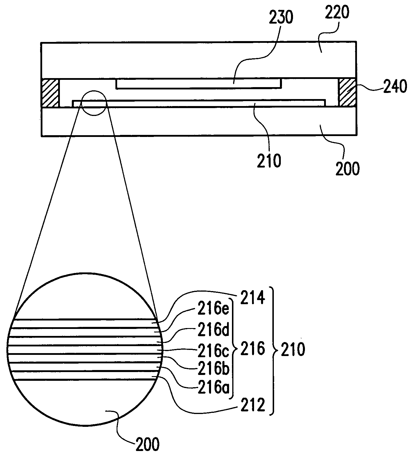
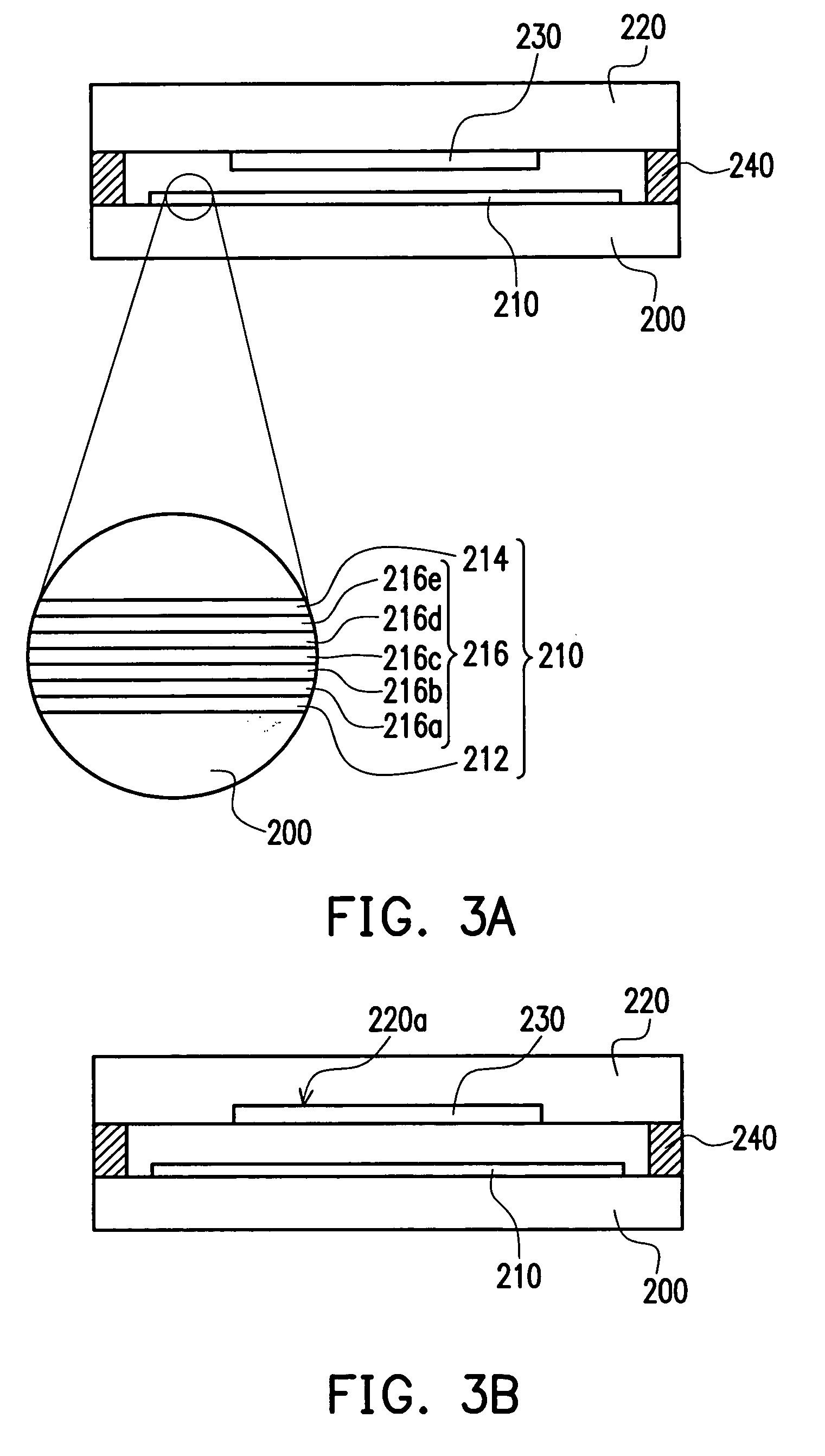
[0015] In one embodiment of the present invention, the desiccant may be disposed above the plate surface. Alternatively, a groove may be formed on the cover plate and then the desiccant is disposed in the groove. Accordingly, the total thickness of the package structure can be reduced.
[0023] Accordingly, in the present invention, the hydrophilic polymer is provided as the desiccant in the package structure of the OEL device. Since the hydrophilic polymer is hydrophilic, moisture or oxygen in the package structure will be readily removed. Therefore, the generation of the dark spots can be effectively reduced, and the lifetime of the OEL device can be effectively enhanced.

Problems solved by technology

In general, a degradation of OEL components leads to formation of dark spots.
First, if the desiccant is a solid desiccant (e.g., including zeolite), the OEL component may be damaged or scrubbed during the process of package.
Therefore, the byproducts may damage the OEL component.
Since some of the desiccant particles are covered by the binders of the solid thin film, a part of the moisture and the oxygen infiltrated in the package structure can not be absorbed rapidly and effectively by the desiccant of the solid thin film.
In other words, the OEL component may be damaged by moisture and oxygen within the package structure due to the low efficiency of the desiccant particles.
Furthermore, as the thickness of the OEL component of the flat panel display device increases gradually, the amount of the solid particles of the desiccant is limited.
However, the efficiency of the conventional desiccant particles is not sufficiently high enough in removing moisture and oxygen within the package structure to protect OEL component of the flat panel display from damage.

Method used


Image

  • Package structure of organic electroluminescent device and package method thereof
  • Package structure of organic electroluminescent device and package method thereof
  • Package structure of organic electroluminescent device and package method thereof

Examples


Embodiment Construction

[0031] The present invention will be described fully hereinafter with reference to the accompanying drawings, in which preferred embodiments of the present invention are illustrated. The present invention may, however, be embodied in many different forms and should not be construed as limited to the embodiments set forth herein; rather, these embodiments are provided so that this disclosure will be thorough and complete, and will fully convey the scope of the invention to those skilled in the art. Like numbers refer to like elements in the accompanying drawings throughout.

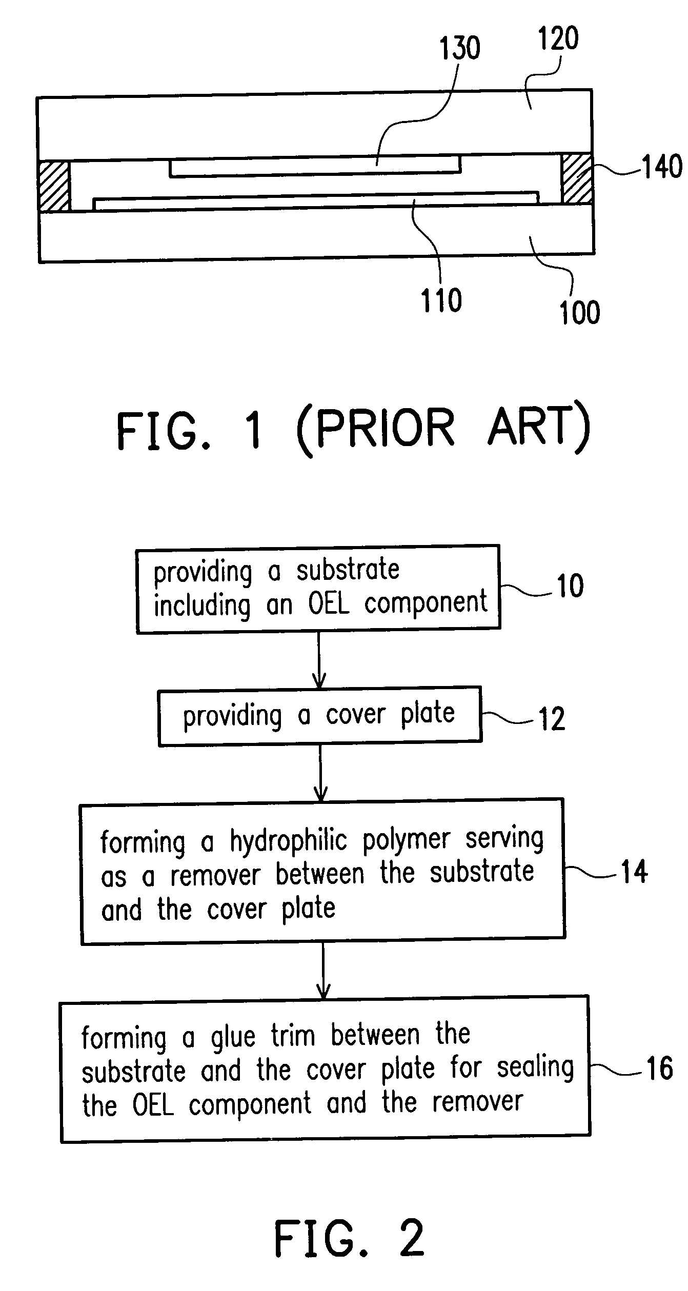
[0032]FIG. 2 is a flowchart illustrating a method of packaging an organic electroluminescent (OEL) component according to one embodiment of the present invention. Referring to FIG. 2, at step 10, a substrate having an organic electroluminescent (OEL) component formed thereon is provided. Thereafter, at step 12, a cover plate is provided. In one embodiment of the present invention, the substrate and the cover plate...


PUM

PropertyMeasurementUnit
Temperatureaaaaaaaaaa
Efficiencyaaaaaaaaaa

Abstract

A package structure of an organic electroluminescent (OEL) device and a method of packaging thereof are provided. The package structure includes a substrate, an OEL component, a cover plate, a desiccant and an adhesive. The OEL component is disposed over the substrate. The cover plate is disposed over the substrate. The desiccant is disposed above the substrate or the cover plate. The desiccant includes, for example but not limited to, a hydrophilic polymer. The adhesive is disposed between the substrate and the cover plate, wherein the OEL component and the desiccant are sealed by the substrate, the cover plate and the adhesive. Therefore, moisture / oxygen in the package structure is absorbed and removed by the hydrophilic polymer.

Description

BACKGROUND OF THE INVENTION [0001] 1. Field of the Invention [0002] The present invention relates to a package structure of an organic electroluminescent (OEL) device and a method of packaging an organic electroluminescent (OEL) device. More particularly, the present invention relates to a package structure of an OEL device using hydrophilic polymer as desiccant and a package method thereof. [0003] 2. Description of Related Art [0004] As the development of the semiconductor process advances, display device has become a main stream of electronic device. For example, portable display device has been well developed and adopted in a variety of appliances such as mobile phone, personal digital assistant (PDA) and notebook. Flat panel display (FPD) serves as a communication interface between user and portable device. It is so important that a good portable device will heavily depend on a good display panel. [0005] Flat panel display can be classified into plasma display panel (PDP), liqui...

Claims


Application Information

Patent Timeline
IPC IPC(8): H01L51/52H05B33/04
CPCY10T428/239H01L51/5237H10K59/874H10K50/846
Inventor HUANG, PING-TSUNGHSIAO, HSIA-TSAIHAN, YU-KAICHENG, TUNG-SHENGLIN, YEN-HUA
Owner RITDISPLAY
Learn More