Infusion apparatus

a technology of infusion apparatus and infusion chamber, which is applied in the direction of automatic syringes, process and machine control, instruments, etc., can solve the problems of toxic reaction, cumbersome gravametric methods, and inconvenient use for patients, and achieves convenient use for ambulatory patients, simple construction, and reliable use

Active Publication Date: 2005-12-15
MARSHALL S KRIESEL REVOCABLE TRUST
View PDF85 Cites 119 Cited by
  • Summary
  • Abstract
  • Description
  • Claims
  • Application Information

AI Technical Summary

Benefits of technology

[0020] Another object of the invention is to provide a fluid dispenser which is adapted to be used with conventional prefilled drug containers to deliver beneficial agents therefrom in a precise and sterile manner.
[0021] Another object of the invention is to provide a fluid dispenser of the class described which is compact, lightweight, is easy for ambulatory patients to use, is fully disposable, and is extremely accurate so as to enable the infusion of precise doses of medicament over prescribed periods of time.
[0022] Another object of the invention is to provide a device of the character described which embodies a novel fluid volume indicator that provides a readily discernible visual indication of the volume of fluid remaining in the device reservoir
[0023] Another object of the invention is to provide a self-contained medicament dispenser which is of very simple construction and yet extremely reliable in use.
[0024] Another object of the invention is to provide a fluid dispenser as described in the preceding paragraphs which is easy and inexpensive to manufacture in large quantities.

Problems solved by technology

Such gravametric methods are cumbersome, imprecise and require bed confinement of the patient.
Certain classes of new pharmacologic agents possess a very narrow range of therapeutic effectiveness, for instance, too small a dose results in no effect, while too great a dose can result in a toxic reaction.
This cumbersome and tedious procedure creates an unacceptable probability of debilitating complications, particularly for the elderly and the infirm.

Method used


Image

  • Infusion apparatus
  • Infusion apparatus
  • Infusion apparatus

Examples


Embodiment Construction

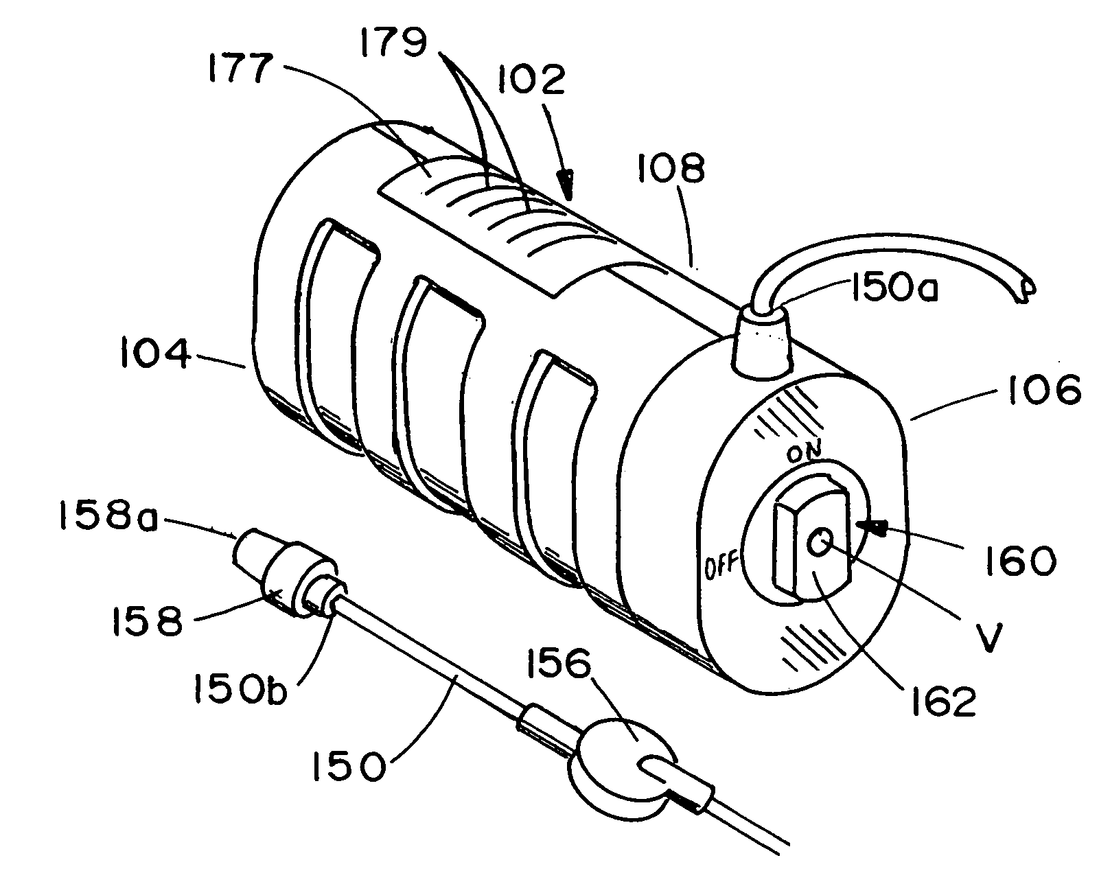
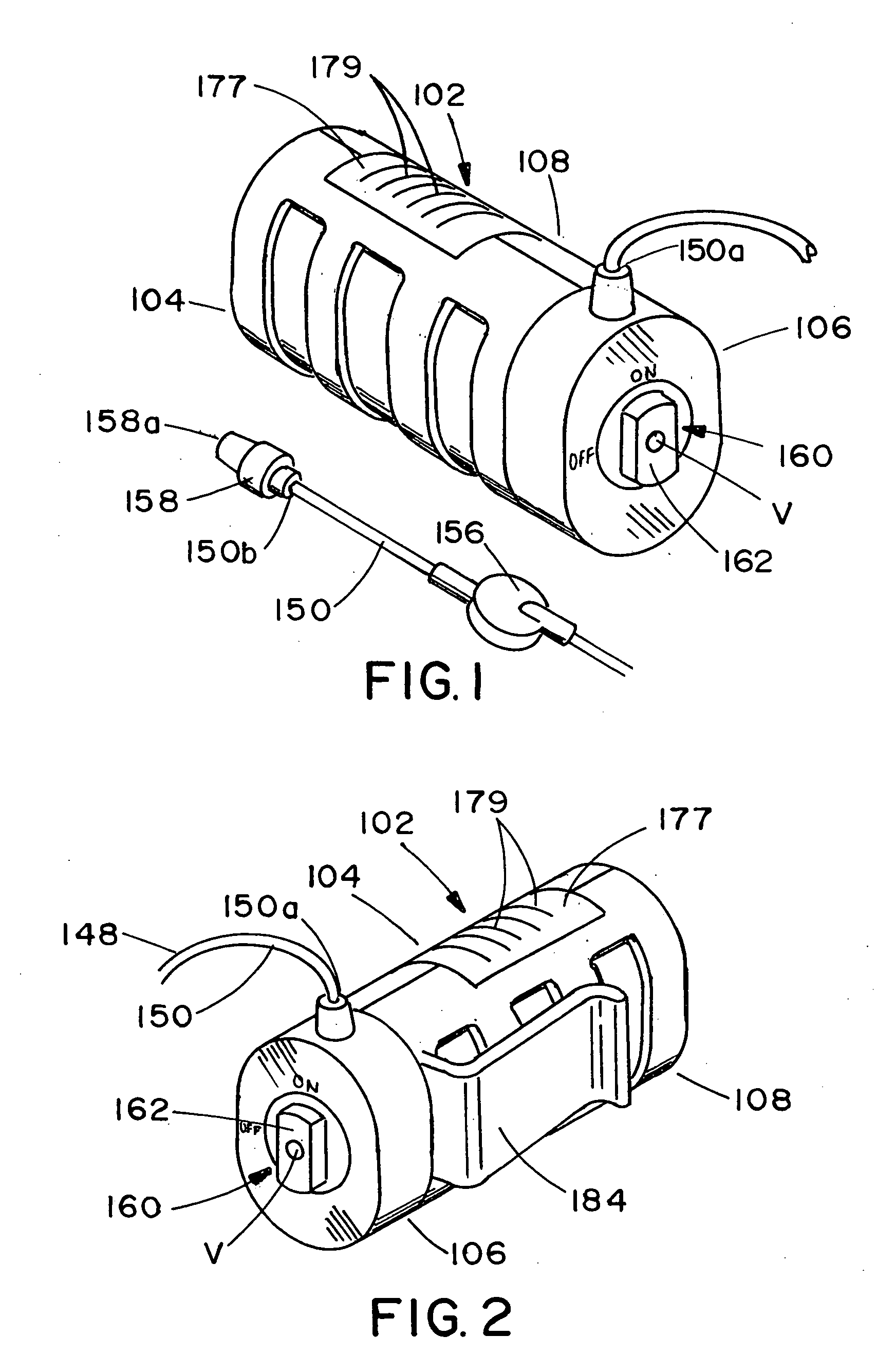
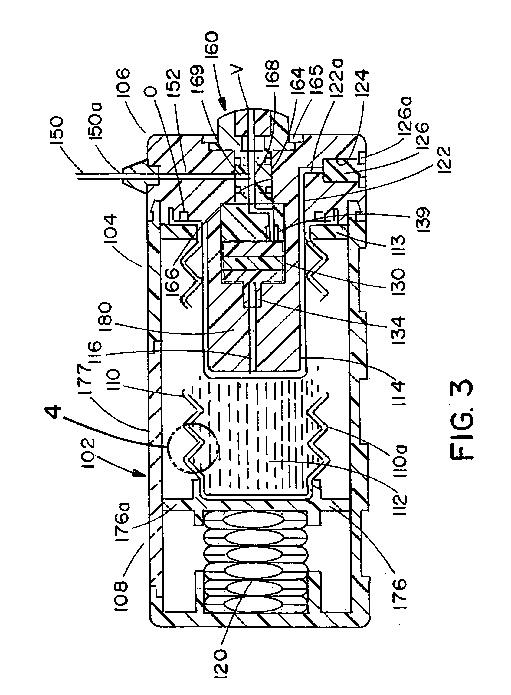
[0142] Referring to the drawings and particularly to FIGS. 1 through 10, one embodiment of the dispensing apparatus of the present invention is there illustrated and generally designated by the numeral 102. As best seen in FIGS. 1 and 2, the apparatus here comprises an outer housing 104 having first and second portions 106 and 108 respectively that can be snapped together, adhesively bonded, sonic bonded or otherwise suitably interconnected. Disposed within outer housing 104 is an inner, expandable housing 110 having a fluid reservoir 112 provided with an inlet 114 (FIG. 3) for permitting fluid flow into the fluid reservoir and an outlet 116 for permitting fluid flow from the fluid reservoir. Expandable housing 110, which can be constructed from a metal or plastic material, comprises a bellows structure having an expandable and compressible, accordion-like, annular-shaped sidewall 110a, the configuration of which is best seen in FIGS. 3 and 4. As best seen in FIG. 4, the inner wall ...


PUM


Abstract

A compact fluid dispenser for use in controllably dispensing fluid medicaments, such as, antibiotics, oncolytics, hormones, steroids, blood clotting agents, analgesics, and like medicinal agents from prefilled containers at a uniform rate. The dispenser uniquely includes a stored energy source that is provided in the form of a substantially constant-force, compressible-expandable wave spring that provides the force necessary to continuously and uniformly expel fluid from the device reservoir. The device further includes a fluid flow control assembly that precisely controls the flow of medicament solution to the patient.

Description

BACKGROUND OF THE INVENTION [0001] 1. Field of the Invention [0002] The present invention relates generally to medicament infusion devices. More particularly, the invention concerns an improved apparatus for infusing medicinal agents into an ambulatory patient at specific rates over extended periods of time, which apparatus includes a novel compressible spring energy source, and a novel flow rate control means for precisely controlling the rate of fluid flow from the reservoir of the device. [0003] 2. Discussion of the Prior Art [0004] A number of different types of medicament dispensers for dispensing medicaments to ambulatory patients have been suggested. Many of the devices seek either to improve or to replace the traditional gravity flow and hypodermic syringe methods, which have been the standard for delivery of liquid medicaments for many years. [0005] The prior art gravity flow methods typically involve the use of intravenous administration sets and the familiar flexible solu...

Claims


Application Information

Patent Timeline
Patent Type & Authority Applications(United States)
IPC IPC(8): A61M5/14A61M5/142A61M5/145A61M5/148A61M5/168A61M5/20A61M5/24A61M37/00A61M39/22
CPCA61M5/141A61M5/14244A61M5/148A61M5/2448A61M2207/00A61M2005/14506A61M2205/0244A61M2205/7545A61M39/22
Inventor KRIESEL, MARSHALL S.
Owner MARSHALL S KRIESEL REVOCABLE TRUST
Why Eureka
Try Eureka