Task scheduling apparatus in distributed processing system

a task scheduling and distributed processing technology, applied in multi-programming arrangements, digital computer details, instruments, etc., can solve the problems of increasing the generated heat quantity of the processor, increasing the consumption power of the processor, and increasing the temperature of the processor

Inactive Publication Date: 2005-12-15
FUJITSU LTD
View PDF11 Cites 201 Cited by
  • Summary
  • Abstract
  • Description
  • Claims
  • Application Information

AI Technical Summary

Benefits of technology

[0013] According to the first aspect of the present invention, because a task is allocated to a processing unit having the lowest temperature or the lowest consumption power, the processing unit having the lowest temperature or the lowest consumption power generates heat as the task is being processed, and thus the temperature of the processing unit of interest is increased. On the other hand, because a task is not allocated to other processing units having higher temperature or higher consumption power, the heat quantity is decreased in these processing units. As a result, it becomes possible to make the temperature of each processing unit equalized.
[0019] According to the second aspect of the present invention, a task is allocated based on both the temperature or the consumption power of each processing unit and the characteristic value of a task related to the degree of the temperature rise or the consumption power increase in each processing unit produced by the execution of each task. For example, a task having a characteristic value representing a small degree of the temperature rise or the consumption power increase is allocated to a processing unit having a high temperature or high consumption power. Or, to a processing unit having a low temperature or low consumption power, the task allocation is performed in an opposite manner. In such a way, it becomes possible to make the temperature of each processing unit equalized.

Problems solved by technology

In recent years, with remarkably improved performance of a processor such as CPU and MPU, processor consumption power is increasing.
This increases generated heat quantity of the processor, and causes a problem of temperature rise of processor.
However, an increased thermal design power (TDP) resulting from improved processor performance has caused a larger fan size and a larger volume of the housing.
As a result, a problem of increased cost of the overall equipment has been produced, as well as increased equipment size.
However, this measure is not recommendable because processing capacity of the processor is inevitably deteriorated.
At the same time, a particular problem arises because of the provision of the plurality of processing units.
As a result, it becomes necessary to attach fans onto all processors as mentioned above, which brings about a large cost increase.
Also, when the method of the voltage or frequency reduction is adopted, it becomes meaningless to provide a multiprocessor configuration with a plurality of processors or a distributed computing environment to increase the processing speed.

Method used


Image

  • Task scheduling apparatus in distributed processing system
  • Task scheduling apparatus in distributed processing system
  • Task scheduling apparatus in distributed processing system

Examples


first embodiment

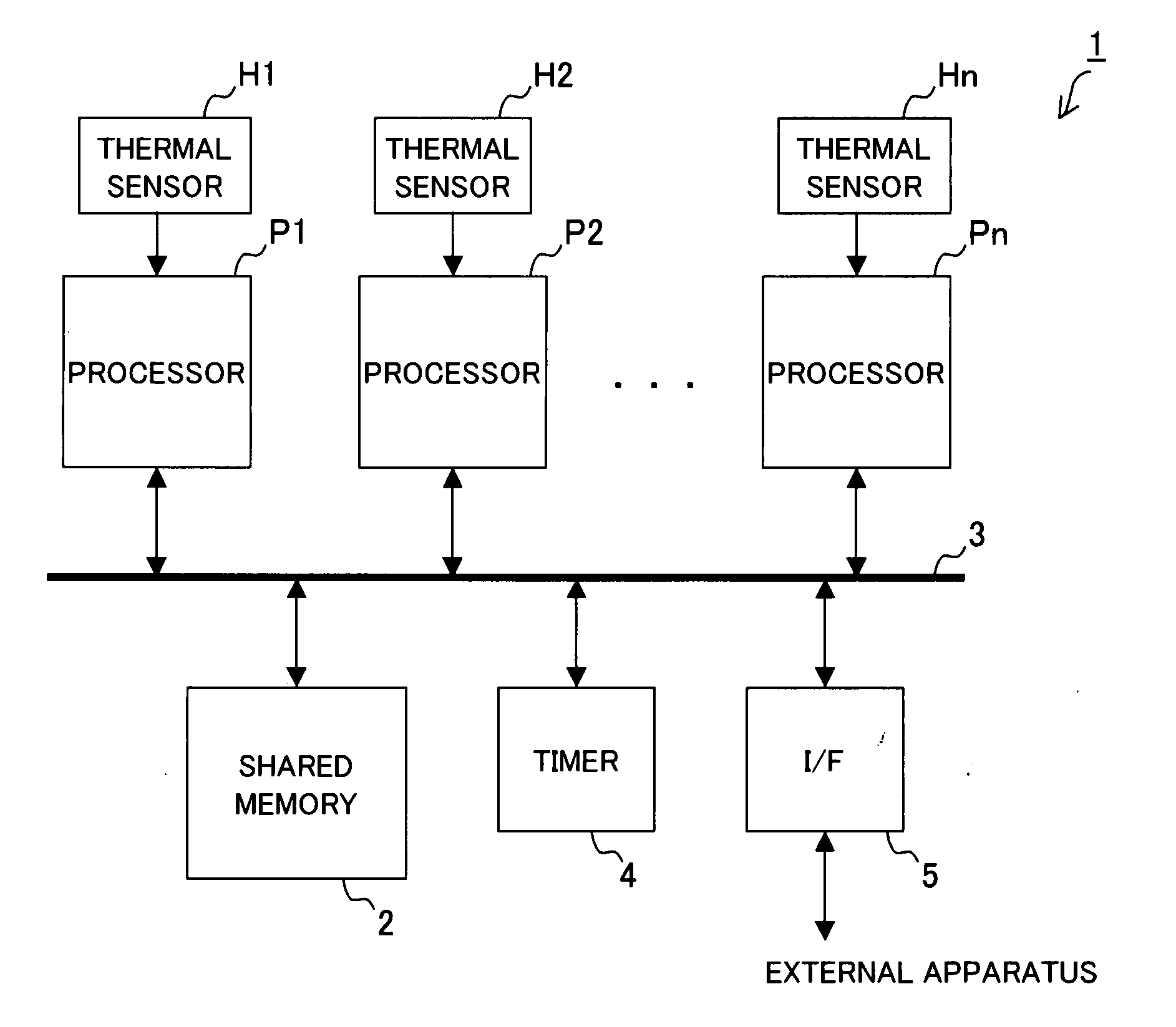
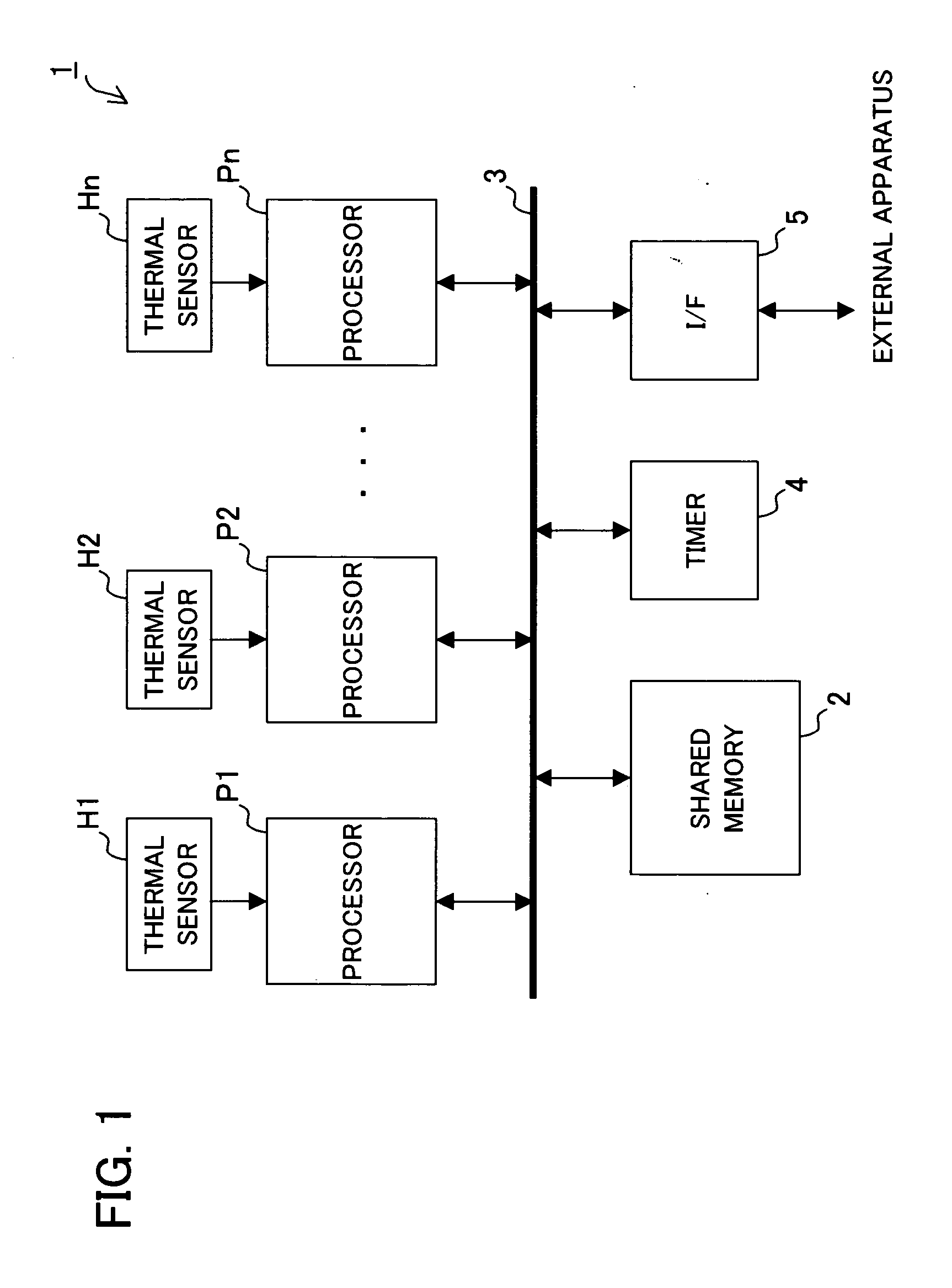
[0027]FIG. 1 shows a block diagram illustrating an exemplary configuration of a distributed processing system according to a first embodiment of the present invention. This distributed processing system 1 is, for example, a multiprocessor system in a single housing, and includes n processors P1-Pn (where n is an integer of 2 or more, the same being applicable hereafter), n thermal sensors H1-Hn, a shared memory 2, a bus 3, a timer 4, and a communication interface unit (I / F) 5.

[0028] Processors P1-Pn, shared memory 2, timer 4, and I / F 5 are connected to bus 3. Through bus 3, processors P1-Pn read out a program or a data stored in shared memory 2, or write a program or a data generated through processing into shared memory 2.

[0029] Each processor P1-Pn is exemplarily configured of CPU, MPU, or the like, or an apparatus (for example, a processor board) configured of CPU, MPU, or the like, with its peripheral hardware circuits. This processor has a memory (including a cache memory) in...

second embodiment

[0096]FIG. 5 shows a block diagram illustrating an exemplary configuration of a distributed processing system according to a second embodiment of the present invention. This distributed processing system 10 is a distributed computing system including a controller 11, n nodes N1-Nn, and a communication network 12.

[0097] Nodes N1-Nn and controller 11 are connected to communication network 12, and can communicate mutually via communication network 12. Communication network 12 is exemplarily constituted of LAN, Internet, etc.

[0098] Each node N1-Nn is, for example a computer, including a processor 21 constituted of CPU, MPU, etc., communication interface unit (I / F) 22 for performing communication interface processing, and a thermal sensor 23 for measuring temperature of processor 21.

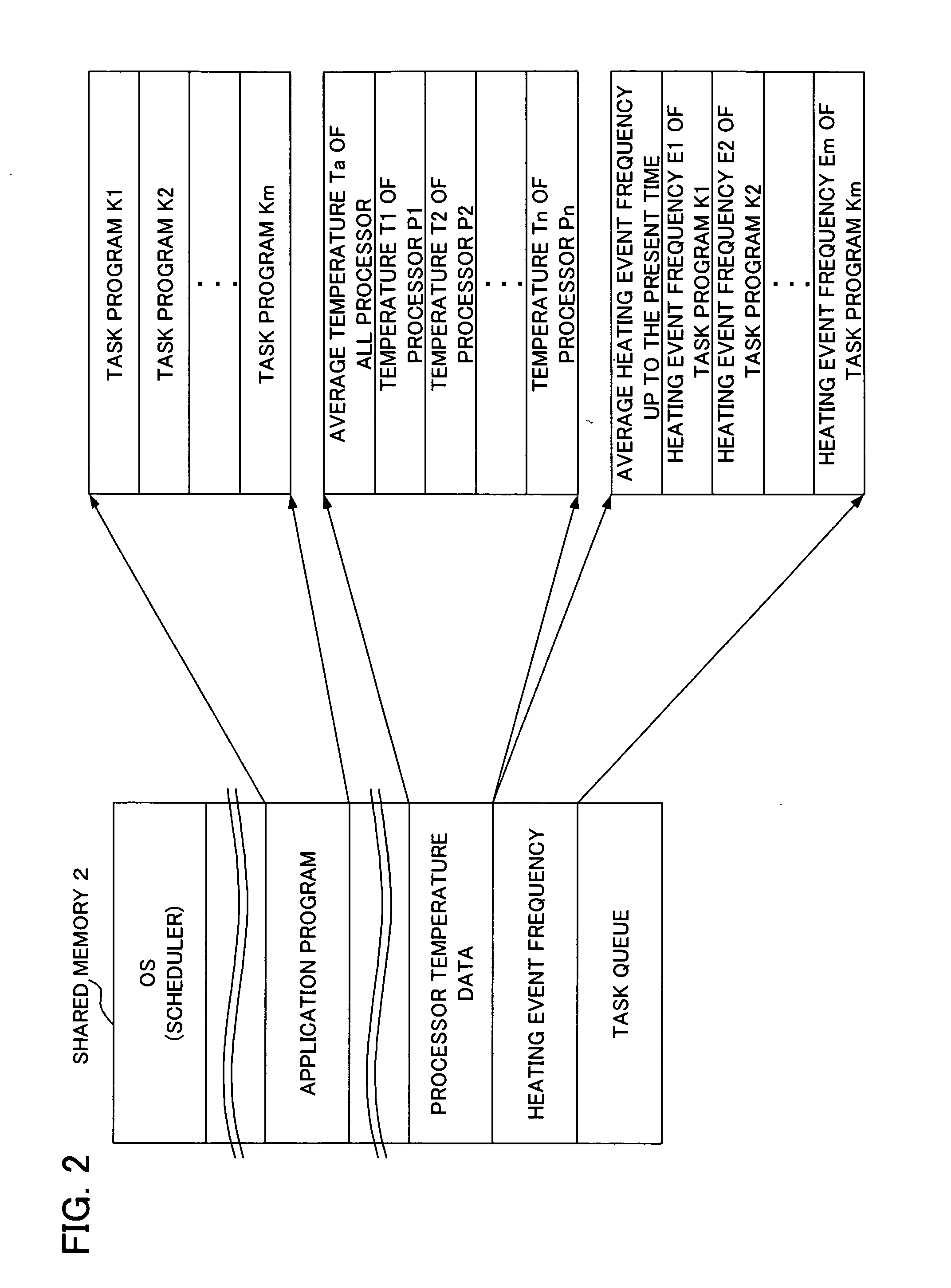
[0099] Controller 11 is, for example a computer, of which internal memory (not shown) has data identical to the data in shared memory 2 shown in FIG. 2. Namely, the internal memory has the OS including the...


PUM


Abstract

A task scheduling apparatus of a distributed processing system having a plurality of processing units for processing a plurality of distributed tasks is provided. As a first task scheduling method, the task scheduling apparatus allocates a task to a processing unit having the lowest temperature. As a second task scheduling method, the task scheduling apparatus selects a task based on both temperature of each processing unit and characteristic values of tasks related to degree of temperature rise or consumption power increase caused by execution, and allocates the selected task to the object processing unit. For example, as the second task scheduling method, a task producing a large degree of temperature rise (for example, a task having a number of instructions to be processed per unit time) is allocated to a processing unit having a low temperature. With such a scheduling method, uniform temperature of each processing unit can be obtained.

Description

FIELD OF THE INVENTION [0001] The present invention relates to a task scheduling apparatus and a task scheduling method, and more particularly a task scheduling apparatus and a task scheduling method in a distributed processing system having a plurality of processing units for distributing and processing a plurality of tasks. The present invention also relates to a program for enabling a computer to execute the task scheduling. BACKGROUND OF THE INVENTION [0002] In recent years, with remarkably improved performance of a processor such as CPU and MPU, processor consumption power is increasing. This increases generated heat quantity of the processor, and causes a problem of temperature rise of processor. [0003] In order to prevent such temperature rise of the processor, measures against heat have been taken to the processor. Such measures include mounting a fan onto the processor, and optimizing airflow inside the housing of the processor. However, an increased thermal design power (T...

Claims


Application Information

Patent Timeline
IPC IPC(8): G06F1/20G06F1/32G06F9/00G06F9/48
CPCG06F1/206G06F1/3203Y02B60/144G06F9/4893Y02B60/1275G06F1/329Y02D10/00
Inventor HIRAI, AKIRAKUMON, KOUICHI
Owner FUJITSU LTD
Why Eureka
Try Eureka