Helmet

a head protection and helmet technology, applied in the field of head protection, can solve the problems of motorcycle helmets becoming very uncomfortable, motorcycle riders complaining about the heat retention properties of today's helmets, and the comfort of motorcycle helmets, so as to improve the air flow through the helmet, improve the air flow, and speed up the effect of speed

Inactive Publication Date: 2005-12-22
TROY LEE DESIGNS
View PDF6 Cites 46 Cited by
  • Summary
  • Abstract
  • Description
  • Claims
  • Application Information

AI Technical Summary

Benefits of technology

[0016] Since the at least one opening is formed in the eye opening, the opening can be quite large and capable of gathering a substantial amount of air. Moreover, since the at least one opening has a component that is perpendicular to the direction of travel, air can be injected into the channels at a relatively high rate of speed thereby improving air flow through the helmet.
[0017] In another aspect of the invention, an intake plenum is formed on the intake surface of the helmet. The intake plenum in one embodiment is comprised of a plurality of openings formed along the eye opening so as to be able to gather air for subsequent delivery into the channels. The use of such an intake plenum results in better air flow through the helmet.
[0018] In another aspect of the invention, the helmet further comprises a liner that is interposed between the inner protective layer and the operator's head. The liner is preferably inhibited from being pushed into the channels at a position proximate the user's forehead when the user is wearing the helmet so as to allow for better air flow through the channels. Moreover, the liner is attached, in one aspect, to the helmet via attachment tabs that are sized so as to be positioned within mating openings. The attachment tabs include a surface that is perpendicular to the plane of the attachment tab that mates with a mating surface in the helmet. Hence, the liner can be positioned within the helmet and secured therein more easily as a result of the tabs being mated with the openings.
[0019] In yet another aspect of the invention, the outer shell of the helmet defines a first air flow surface and a second air flow surface wherein the air flows over the second surface at a slower rate than the first surface. The exhaust openings are, in this aspect, preferably positioned on the second surface immediately adjacent the interface with the first surface such that a relative vacuum is formed adjacent the exhaust openings to thereby facilitate removal of the air. In this aspect, air flow through the helmet is enhanced as a result of the relative vacuum.

Problems solved by technology

While some prior art motorcycle helmets meet the safety standards and provide protection against head injuries, prior art motorcycle helmets are uncomfortable for a number of reasons.
For many years, motorcycle riders have complained about the heat retention properties of today's helmets.
Especially for riders in warm climates, motorcycle helmets become very uncomfortable as they trap heat around a person's head.
Not only does the heat retention in today's helmets causes excessive perspiration from the heads of riders, it can lead to heat exhaustion, limiting the length of time a rider can enjoy off-road riding.
These holes are often ineffective because they simply do not allow enough air into the head cavity to provide significant cooling to the user.
Unfortunately, these air scopes typically have very small openings, often about ⅛ inch or ¼ inch, and therefore catch very little air and are similarly less effective in flowing cooling air into the head cavity.
Further, today's helmets have limited air flow within the helmet itself.
In particular, helmets on the market today have small channels that are easily occluded by the liner.
Moreover, the channels are often formed in such a manner that continuous air flow through the channels is disrupted.
As such, these helmets have less effective channeling systems such that any air that does enter the head cavity simply cannot create the airflow needed to adequately cool a user's head.
Furthermore, today's helmets are not very effective in removing heated air and perspiration from the head cavity.
Most helmets on the market today have small exhaust openings that are not particularly effective in permitting the air from the inside of the helmet to be removed.
Additional problems with today's helmets relate to the helmet liners included in helmets as a soft cushion between a user's head and the helmet's impact absorbing layer.
The liners in today's helmets are often pressed against the impact absorbing layer by a user's head such that the liner impedes, or sometimes even blocks, airflow in the head cavity.
This problem is amplified when the liner becomes saturated with sweat as a wet liner will adhere to the impact absorbing layer and allow even less air through an air channel than a dry liner.
Further, a sweat saturated liner is uncomfortable against a riders head.
While liners are typically removable and replaceable, poor design of today's liners makes removal and replacement inconvenient.
This design makes replacing a helmet liner a time consuming and bothersome chore.
In sum, today's helmets are not very effective in addressing the problem of heat retention associated with helmets.
The problem of heat retention in helmets often leads riders to loosen the fit of their helmets or even remove their helmets while riding, thereby defeating the safety function.

Method used


Image

  • Helmet
  • Helmet
  • Helmet

Examples


Embodiment Construction

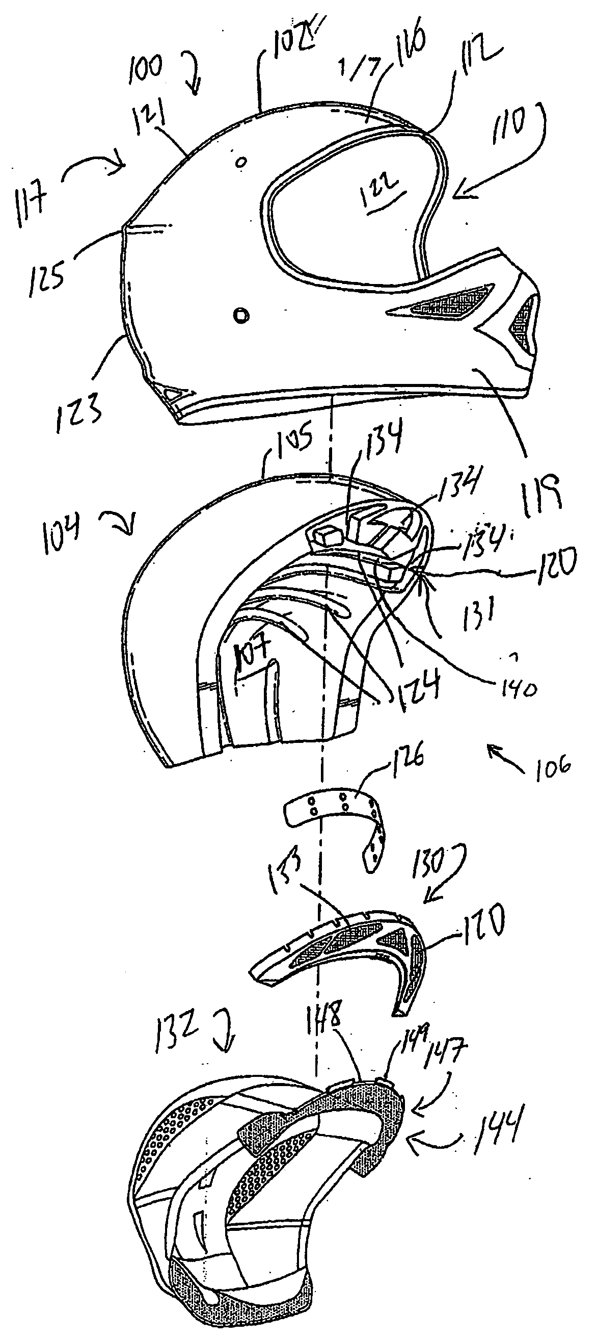
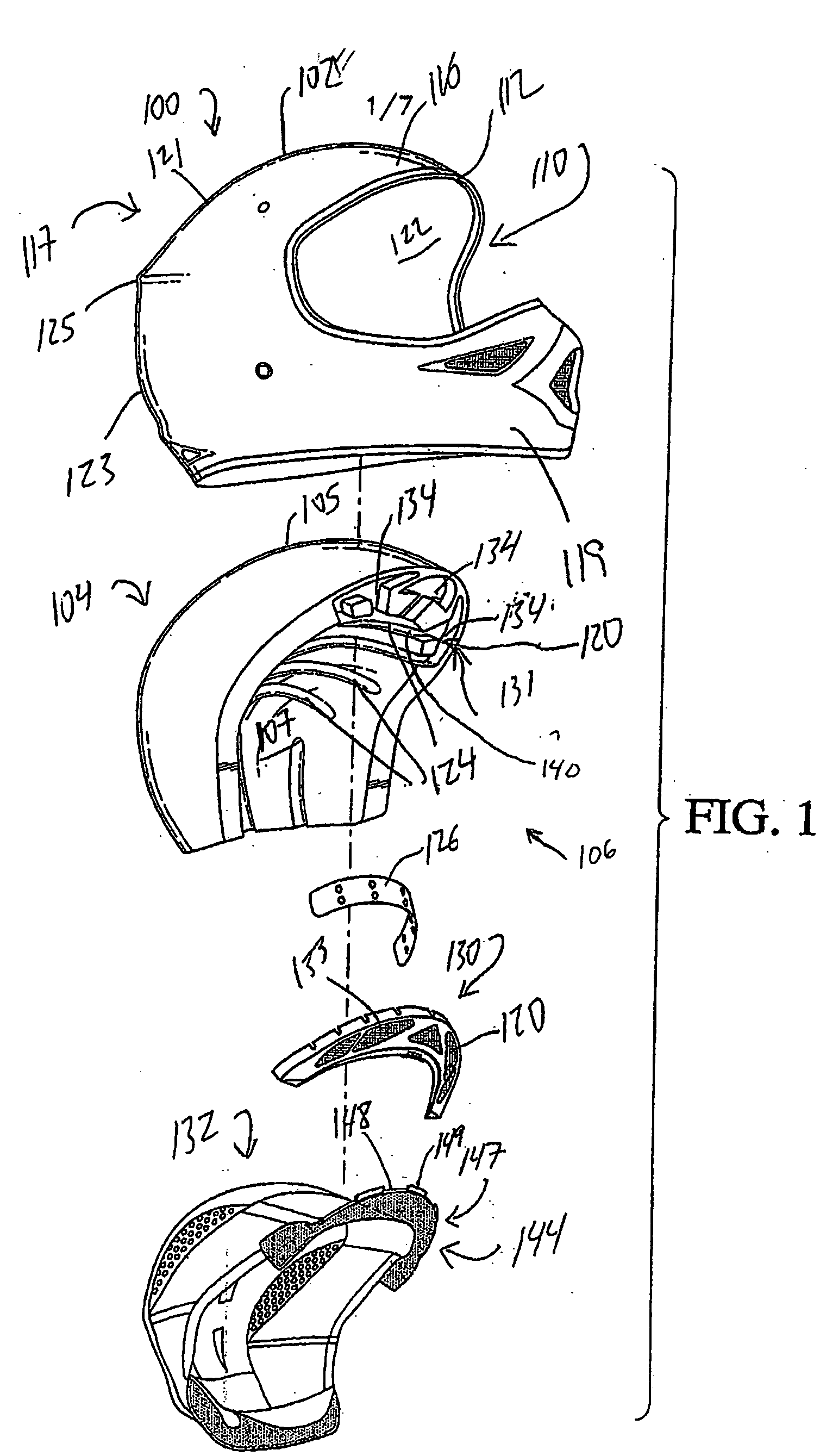
[0029] Reference will now be made to the drawings wherein like numerals refer to like parts throughout. FIG. 1 illustrates an exploded view of the disclosed helmet 100 according to one embodiment. FIG. 1 illustrates an outer protective shell 102 and an inner protective layer 104 which combine to form a head cavity 106. The outer shell 102 includes an eye opening 110, through which a user can see while wearing the helmet, an eye opening perimeter 112, and at least one exhaust opening 114, not shown in FIG. 1. The outer shell may also include a forehead member 116 located at or near the eye opening perimeter 112.

[0030] As illustrated in FIG. 1, the outer shell 102 includes a skull protection section 117 and a chin protector 119 with the eye opening 106 interposed therebetween. The chin protector 119 is integrally attached to the skull protection section 117 and extends outward therefrom in a known manner and is positioned so as to provide protection to the lower face of the user when...


PUM


Abstract

A helmet that ventilates a user's head more efficiently. The relative movement of the helmet to air in the environment creates an airflow that enters intake openings designed to allow increased amounts of airflow into the helmet. The intake openings are positioned on an inclined plane near a user's forehead such that the intake openings extend upwardly and outwardly away from a user's eyes, thereby reducing the impact of a larger intake opening on the user's field of vision. Inside the intake openings, air is collected in a plenum and then guided into air channels leading into the head cavity. The air channels direct the airflow throughout the head cavity allowing the fresh air from the environment to exchange heat and perspiration from a user's head and are designed to inhibit obstruction of the air channels by the liner. Air channels also direct airflow to an exhaust such that the airflow can remove heat and perspiration from the helmet cavity and the helmet surface adjacent the exhaust is contoured to facilitate removal of air from the helmet. The liner is designed for easier installation and replacement.

Description

RELATED APPLICATIONS [0001] The present application claims priority to U.S. Provisional Patent Application Ser. No. 60 / 558241, filed Mar. 31, 2004.BACKGROUND OF THE INVENTION [0002] 1. Field of the Invention [0003] This invention relates to head protection for operators or riders of motorized vehicles. [0004] 2. Description of the Related Art [0005] Use of head protection is often recommended and sometimes required by law while operating motorized vehicles, such as when riding a motorcycle. Helmets are available in a variety of styles but the principle design consideration for all helmets is protection from serious head injuries during accidents. [0006] Generally, motorcycle helmets that comply with the safety standards include a thin, hard outer shell and an impact-absorbing, thicker inner shell made of a rigid foam, such as Expanded Polystyrene (“EPS”). While some prior art motorcycle helmets meet the safety standards and provide protection against head injuries, prior art motorcy...

Claims


Application Information

Patent Timeline
Patent Type & Authority Applications(United States)
IPC IPC(8): A42B3/00A42B3/12A42B3/28
CPCA42B3/283A42B3/12
Inventor LEE, TROY M.
Owner TROY LEE DESIGNS
Why Eureka
Try Eureka