Method and apparatus for evaporative cooling of a cooling fluid

a technology of cooling fluid and cooling method, which is applied in the field of evaporative cooling of cooling fluid, can solve the problems of insufficient cooling effect of compensation water, insufficient cooling of relatively large amount of inflowing air, and limited evaporative cooling temperature of cooling fluid to the wet-bulb temperature of the atmospheric, etc., and achieve the effect of maximizing the cooling efficiency of the cooling apparatus

Inactive Publication Date: 2005-12-22
WHIZEN GLOBAL
View PDF12 Cites 41 Cited by
  • Summary
  • Abstract
  • Description
  • Claims
  • Application Information

AI Technical Summary

Benefits of technology

[0020] Thus, the present invention has been contrived to solve the above problems of the prior arts. An object of the present invention is to reduce the wet-bulb temperature of the air being introduced into the evaporative cooling section by cooling sensibly the introduced outside air without an increase in the humidity using a part of the cooling fluid which has been evaporatively cooled in the evaporative cooling section of a cooling apparatus such as a cooling tower, thereby providing a means for maximizing the cooling efficiency of the cooling apparatus.
[0026] Repeating the aforementioned four steps of cooling, the cooling fluid can be cooled to a temperature even lower than the atmospheric wet-bulb temperature and ideally to the atmospheric dew-point temperature. This is because the inlet air is cooled sensibly without a change in the humidity to reduce its wet-bulb temperature before flowing into the evaporative cooling section. Since the wet-bulb temperature of the inlet air of the evaporative cooling section is lower than that of the atmospheric air, the cooling fluid can be cooled down more effectively to lower temperature than that at the conventional cooling towers. Additionally, if the cooling fluid of the lower temperature is extracted and supplied to the sensible air-cooling section, the inlet air can be cooled even colder to have much lower wet-bulb temperature. Subsequently, the cooling fluid can be cooled even lower down, and ideally, to the atmospheric dew-point temperature if the heat and mass transfer conductance is infinitely large enough in both the sensible air-cooling section and the evaporative cooling section.

Problems solved by technology

For the improved heat and mass transfer, the filler composing the evaporative cooling section 3 and the ventilating fan 5 must be enlarged, which results in an undesirable increase in the external volume of the cooling tower.
However, the pre-cooler 9 of Korean Laid-open Patent Publication No. 10-2003-0032240 has problems as follows:
Therefore, the cooling effect of that small amount of the compensation water is not sufficient enough to cool the relatively large amount of inflowing air even though the temperature of the water is much lower than that of the air.
However, in the above patents, since the inflow air induced from the outside is introduced into the evaporative cooling section without a change of the temperature, the evaporative cooling temperature of the cooling fluid is limited to the wet-bulb temperature of the atmospheric air as usual conventional cooling towers.

Method used


Image

  • Method and apparatus for evaporative cooling of a cooling fluid
  • Method and apparatus for evaporative cooling of a cooling fluid
  • Method and apparatus for evaporative cooling of a cooling fluid

Examples


first embodiment

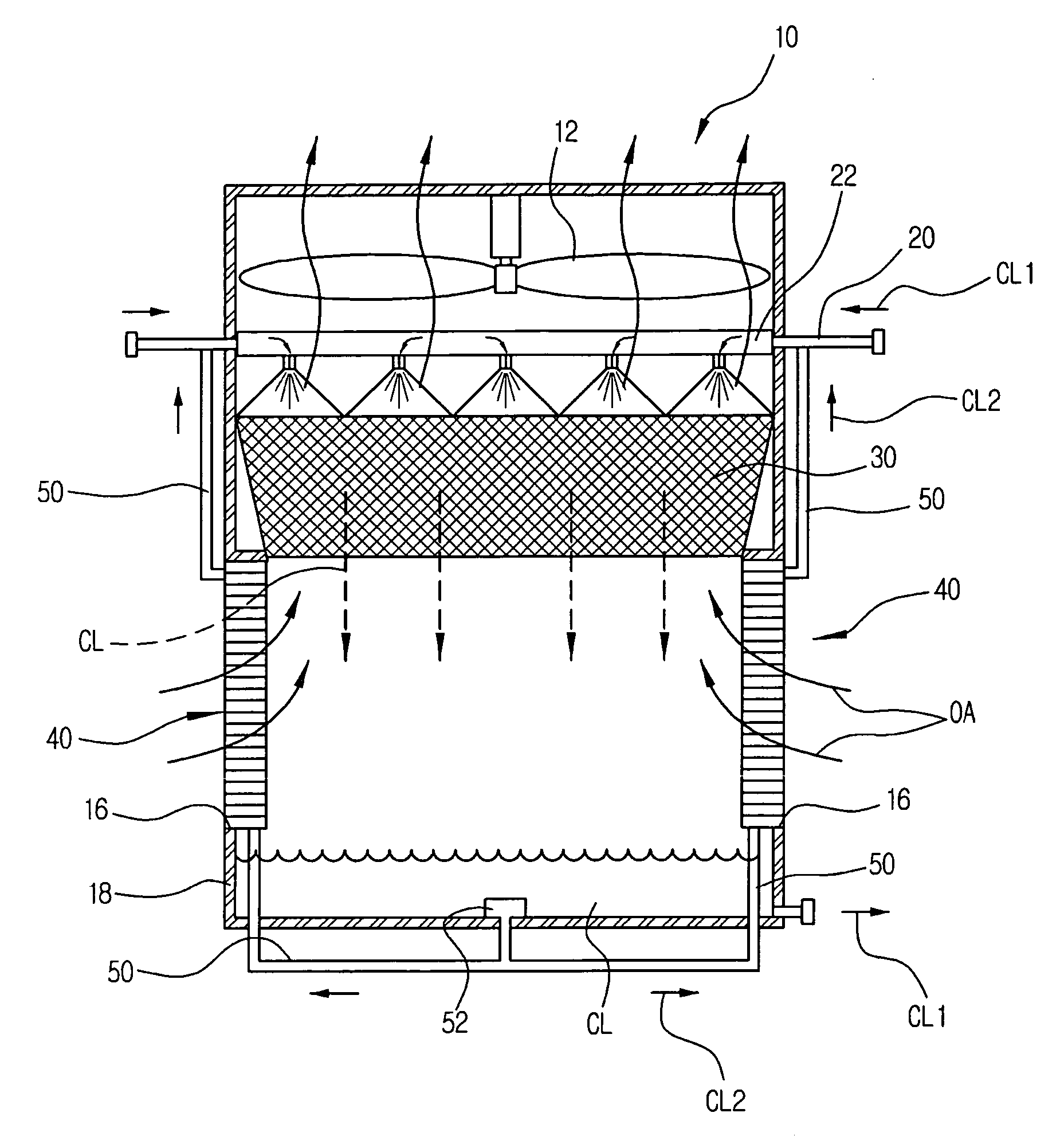
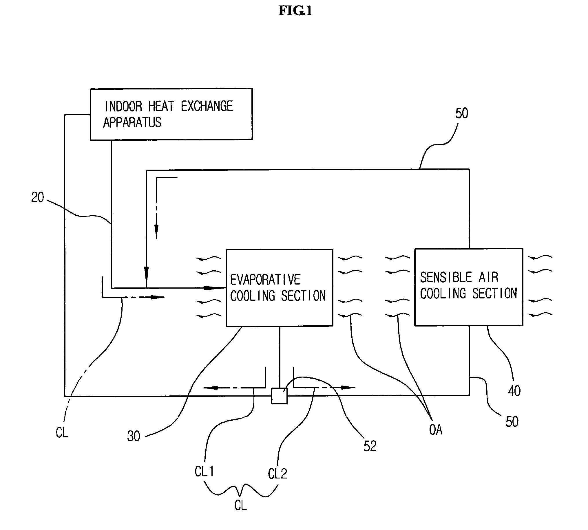
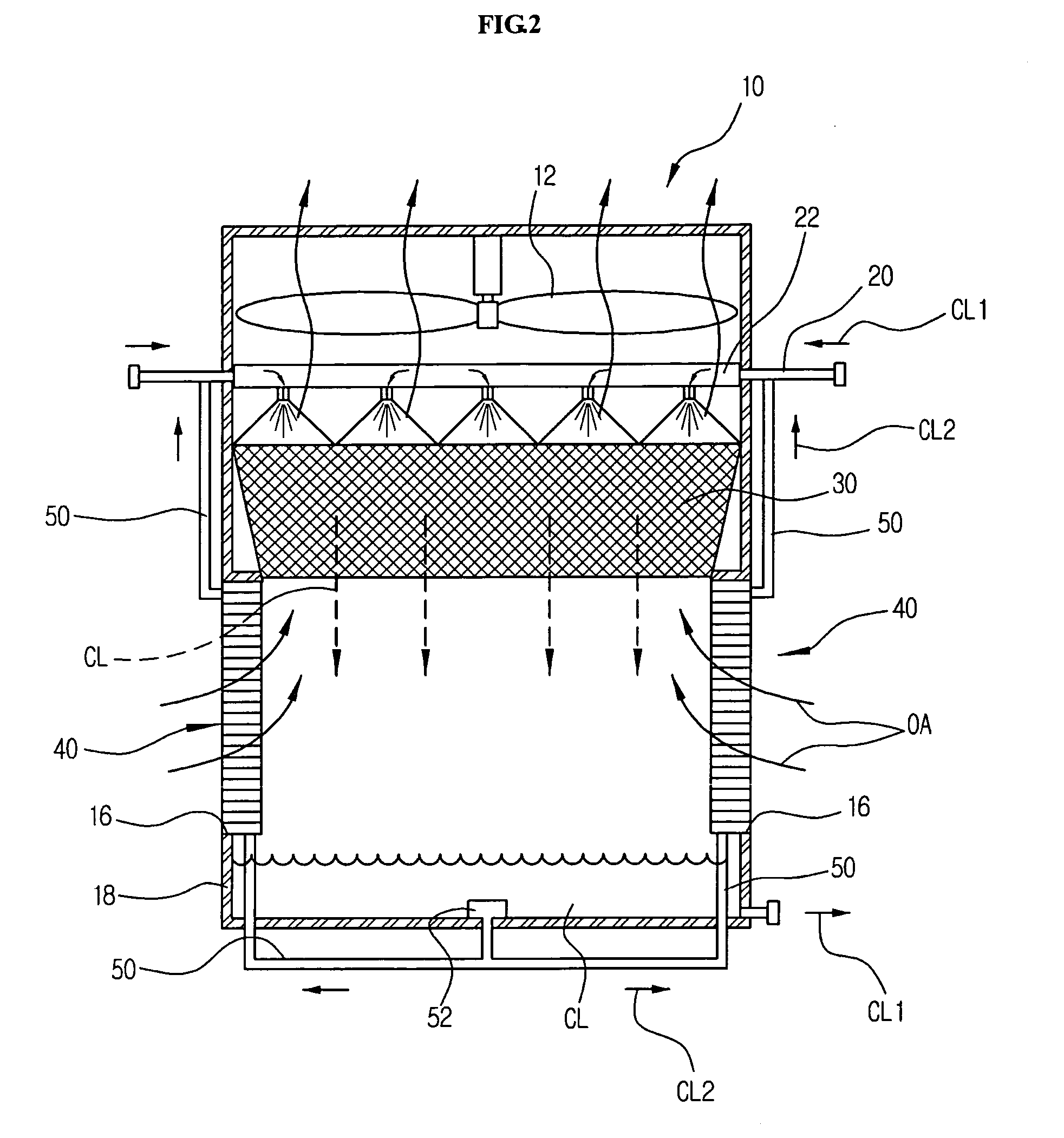
[0049]FIG. 2 shows a constitution of an evaporative cooling apparatus according to a preferred first embodiment of the present invention. Referring to FIG. 2, the apparatus for evaporative cooling of a cooling fluid comprises the evaporative cooling section 30 installed in a cooling tower (=an evaporative cooler) for evaporatively cooling a cooling fluid (CL); the sensible air-cooling section 40 installed at the air inlet 16 of the evaporative cooler 10 for sensibly cooling the outside air (OA) by indirect contact of the second cooling fluid (CL2), which was extracted from the cooling fluid (CL1) having been evaporatively cooled in the evaporative cooling section 30; and a circulating member 50 piped in such a manner that the second cooling fluid (CL2), which has flown out of the sensible air-cooling section 40, re-circulates into the evaporative cooling section 30.

[0050] Herein, the cooling fluid (CL), which has been evaporatively cooled as it passes through the evaporative cooling...

second embodiment

[0080] Meanwhile, FIG. 5 shows a preferred second embodiment according to the present invention.

[0081] As shown in FIG. 5, the preferred second embodiment has the same constitution and operation as the preferred first embodiment except that the cooling fluid (CL) indirectly contacts with the outside air (OA) in the evaporative cooling section 30.

[0082] In other words, as shown in FIG. 5, the evaporation water (EW) instead of the cooling fluid (CL) is supplied to the distribution pipe 22 by means of an EW circulating pump 72 and an EW circulating pipe 70, distributed over the evaporative cooling section 30 and passes there through it. The evaporation water (EW) drips down from the evaporation cooling section 30, collects in the collection sump 18 and is supplied back to the evaporative cooling section 30.

[0083] The cooling fluid (CL) flows through the heat exchange tubes 32 installed in the evaporative cooling section 30 instead of being distributed over the evaporative cooling sec...

third embodiment

[0085] Meanwhile, FIG. 6 shows a preferred third embodiment according to the present invention.

[0086] As shown in FIG. 6, this preferred third embodiment has the same constitution and operation principle as the first embodiment or the second embodiment except that a controlling valve 60 is disposed in the circulating member 50 in order to control the amount of flow of the second cooling fluid (CL2).

[0087] The controlling valve 60 is preferably installed in the circulating member 50 between the circulating pump 52 and the sensible air-cooling section 40, so that it can control the amount of flow of the second cooling fluid (CL2) directed to the sensible air-cooling section 40. The controlling valve 60 is controlled by a separate controlling means and can be constituted of a well-known electronic valve for controlling an amount of flow.

[0088] If the flow amount of the second cooling fluid (CL2) supplied to the sensible air-cooling section 40 is controlled appropriately, the degree o...


PUM


Abstract

A method and an apparatus of evaporative cooling for reducing the volume of an evaporative cooler by considerably lowering the temperature of a cooling fluid are disclosed. A first cooling fluid, which comprises most part of the cooling fluid evaporatively cooled by an outside air while passing through an evaporative cooling section after circulating in an apparatus to be cooled, re-circulates in the apparatus to be cooled. A second cooling fluid, which is separated from the cooling fluid after being cooled in the evaporative cooling section, passes through a sensible air-cooling section placed at an outside air inlet. Thereby, the inflow outside air is sensibly cooled. The second cooling fluid, which passes through the sensible cooling section, re-circulates in the evaporative cooling section. Also, the outside air that is sensibly cooled by the second cooling fluid evaporatively cools the cooling fluid, which passes through the evaporative cooling section, again. This process is repeated. Accordingly, the cooling efficiency in the apparatus to be cooled becomes maximized. The second cooling fluid indirectly contacts with the outside air, so the outside air is sensibly cooled without increasing its humidity. Thus, the wet-bulb temperature of the air inhaled into the evaporative cooling section is reduced and the cooling fluid can be cooled to even a lower temperature. Also, the above structure can provide a cooling fluid of even a lower temperature, so the volume of a cooling tower or outdoor unit, etc. can be reduced considerably.

Description

BACKGROUND OF THE INVENTION [0001] 1. Field of the Invention [0002] The present invention relates to a method and an apparatus for evaporative cooling of a cooling fluid. More particularly, the present invention relates to a method and an apparatus for evaporative cooling of a cooling fluid, which is capable of considerably reducing the volume of an evaporative cooler such as a cooling tower by cooling a cooling fluid to a lower temperature, which has been heated due to heat exchange as it circulated in an apparatus to be cooled in a cooling tower or an indoor or outdoor unit of a general air conditioner, etc. [0003] 2. Description of the Related Art [0004] In cooling systems, a cooling fluid takes heat away from an apparatus to be cooled by absorbing heat from the apparatus as it circulates therein. The cooling fluid heated by this process is cooled by releasing heat through a cooling process such as evaporative cooling and then it is re-circulated to the apparatus to be cooled. [0...

Claims


Application Information

Patent Timeline
Patent Type & Authority Applications(United States)
IPC IPC(8): F28C1/04F24F1/0083F24F5/00F25D17/00F25D17/02F28C1/14F28D5/00
CPCF24F1/0007F24F5/0035F28D5/02Y02B30/545F28C1/14Y02B30/54Y02B30/70F24F1/0083F28C1/04
Inventor LEE, DAE YOUNGLIM, JIN KOOMOON, HYUN KI
Owner WHIZEN GLOBAL
Why Eureka
Try Eureka