
Integrated heat exchanger for use in a refrigeration system

a heat exchanger and refrigeration system technology, applied in the field of refrigeration systems, can solve the problems of affecting fuel economy, limiting the ability of the vehicle's design to achieve aerodynamic slipperiness, and many such systems are prone to refrigerant leakag

Inactive Publication Date: 2005-12-22
MODINE MFG CO
View PDF6 Cites 50 Cited by
  • Summary
  • Abstract
  • Description
  • Claims
  • Application Information

AI Technical Summary

Benefits of technology

[0009] It is the principal object of the invention to provide a new and improved refrigeration system of the multistage compressor type. It is also an obje

Problems solved by technology

However, many such systems have been prone to refrigerant leakage, particularly those in vehicular applications.
Large components limit the ability of the designer of the vehicle to achieve aerodynamic slipperiness which, of course, affects fuel economy as well as the ability to achieve a pleasing appearance.

Method used


Image

  • Integrated heat exchanger for use in a refrigeration system
  • Integrated heat exchanger for use in a refrigeration system
  • Integrated heat exchanger for use in a refrigeration system

Examples


Embodiment Construction

[0032] Before proceeding to the detailed description of the various embodiments, it is to be understood that the term “refrigeration system” as used herein is used in a broad sense to include any vapor compression based system utilized for cooling other objects. It is intended to include not only refrigeration systems in the narrow sense, such as refrigerators, refrigerated vehicles, etc. but also to include systems utilized for cooling spaces and / or occupants of such spaces, more narrowly understood to refer to air conditioning systems.

[0033] It is also to be noted that the invention is applicable to systems employed with refrigerants that in fact substantially fully change from the vapor phase to the liquid phase in a heat exchanger typically termed a condenser as well as in the systems utilizing so called transcritical refrigerants, such as carbon dioxide, wherein true condensation does not fully occur but nonetheless require a gas cooler for cooling the refrigerant after it has...


PUM


Abstract

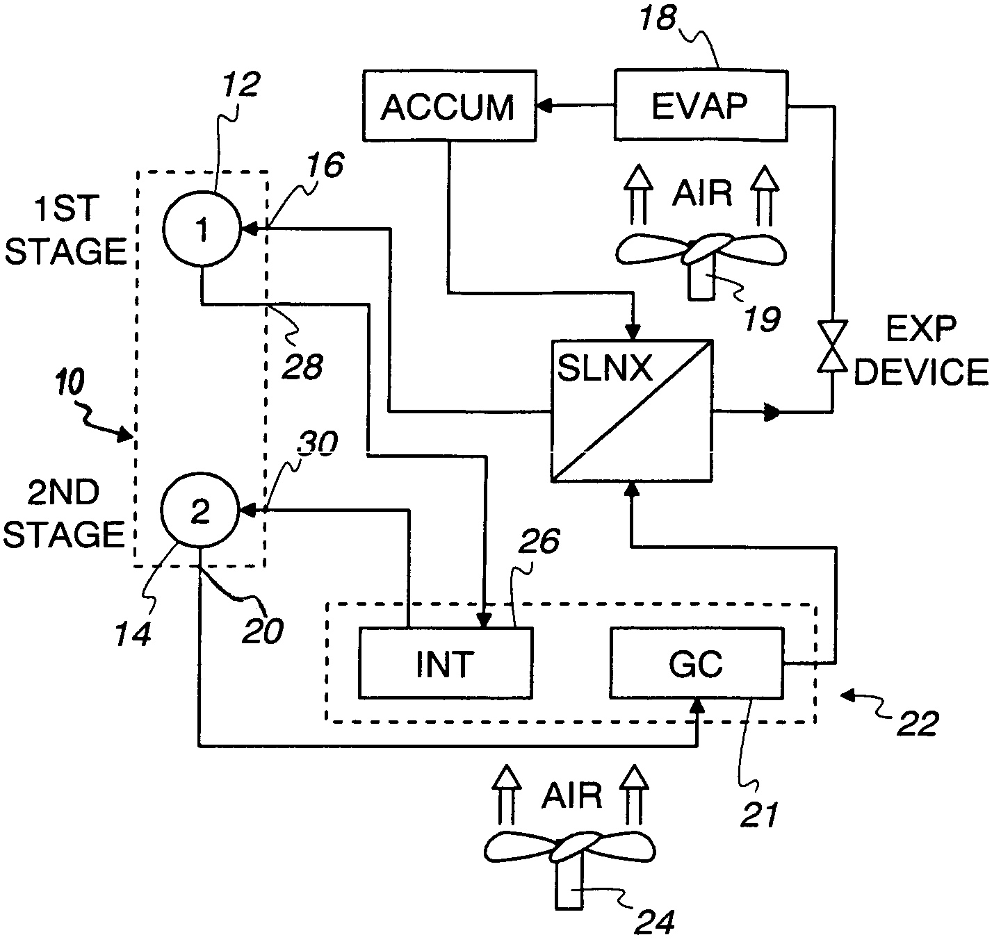
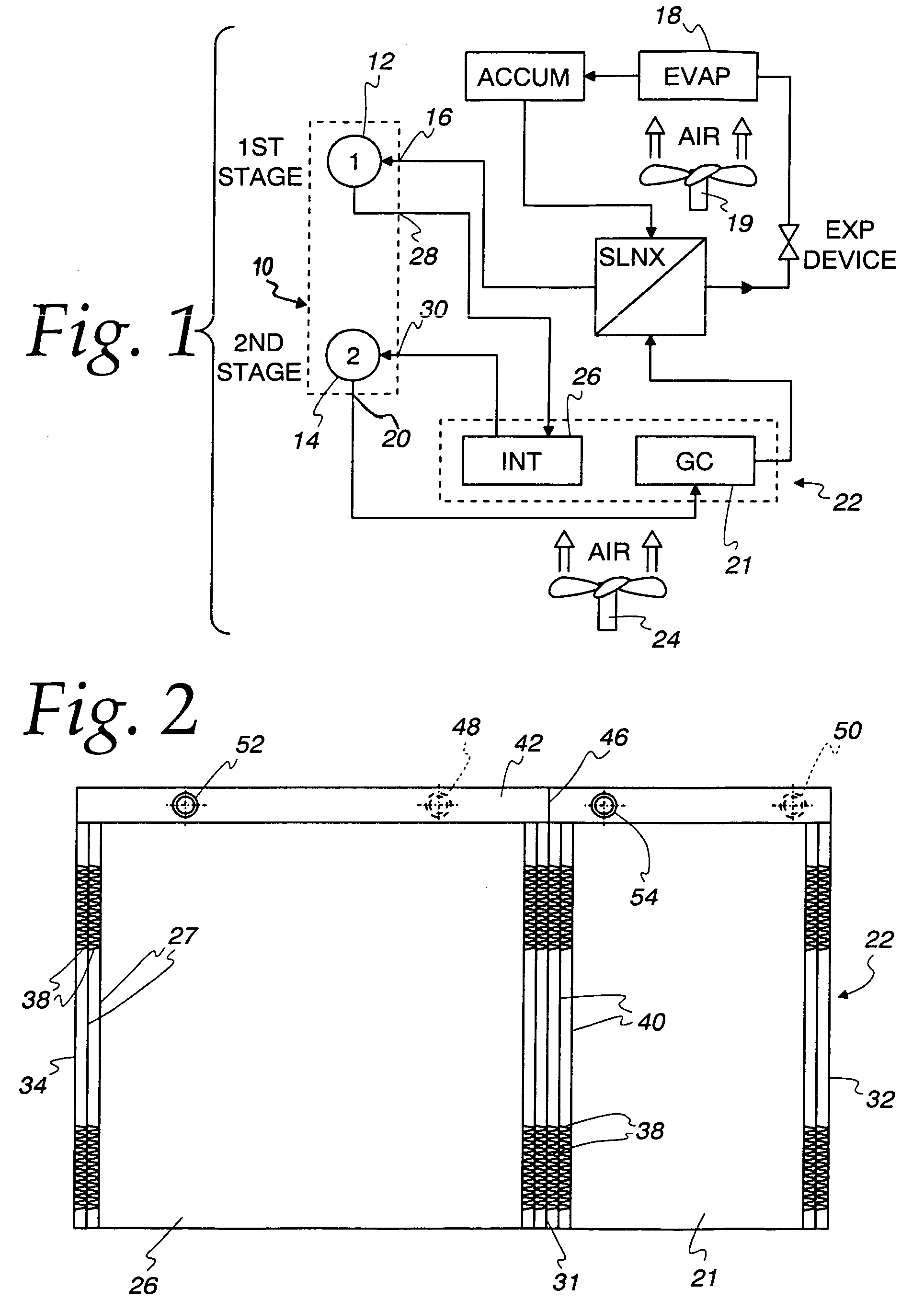
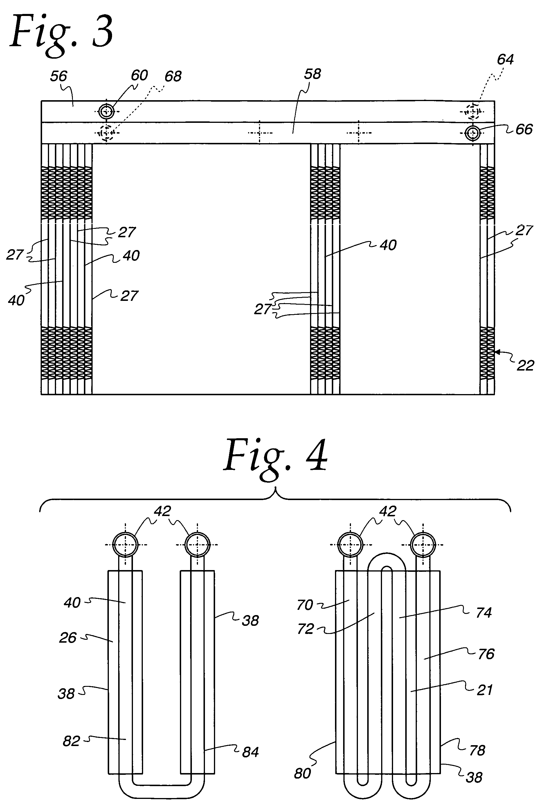
A refrigeration system includes a multiple stage compressor 10 having at least two stages 12,14 for sequentially compressing the refrigerant together with a gas cooler 21 connected to the compressor 10 for receiving compressed refrigerant from the last stage 14 of the compressor to cool the same. An evaporator 18 is connected to the gas cooler 21 via an expansion device to receive cool refrigerant therefrom and cool the fluid stream passing through the evaporator 18. A return passage connects the evaporator 18 to the first stage 12 of the compressor and an intercooler 26 is connected between the first stage 12 and the last stage 14 of the compressor to cool refrigerant compressed by the first stage 12 and direct the refrigerant cooled thereby to the last stage 14 for further compression. The intercooler 26 and the gas cooler 21 are integrated into a single unit 22 and receive a single cooling heat exchange fluid and the gas cooler 21 has a larger heat transfer surface area than the intercooler 26.

Description

FIELD OF THE INVENTION [0001] This invention relates to refrigeration systems and to an integrated heat exchanger for use in such systems. BACKGROUND OF THE INVENTION [0002] Most refrigeration systems (which term, as used herein, is intended to include air conditioning systems) operate on the vapor compression cycle. In such a cycle, a refrigerant is compressed and then the compressed refrigerant cooled before being expanded in an evaporator to cool a heat exchange fluid. The heat exchange fluid may be used to cool various objects, such as the contents of a refrigerator or the occupants of a space. Until relatively recently, common refrigerants were chloro-fluoro carbons (CFC's) or hydro-chloro-fluoro carbons (HCFC's) because of their non combustibility and relatively easy cycling through the system. However, many such systems have been prone to refrigerant leakage, particularly those in vehicular applications. The escaping refrigerant, depending upon the type, is believed to damage...

Claims


Application Information

Patent Timeline
IPC IPC(8): F25B1/10F25B9/00F25B40/00F28D1/04
CPCF25B1/10F25B9/008F25B40/00F28F2009/0287F25B2500/18F28D1/0443F28D2021/0073F25B2309/061F25B9/00F28D1/0408
Inventor JIA, TAOMEMORY, STEPHEN B.YIN, JIANMIN
Owner MODINE MFG CO
Learn More