Planar coupling assembly for an automatic transmission

a technology of automatic transmission and coupling assembly, which is applied in the direction of mechanical actuated clutches, interengaging clutches, gearing, etc., can solve the problems of continuous overrunning of one, wear and undesirable noise, and unwanted movement of the strut, so as to enhance the beneficial holding effect, simplify the design, and improve the freewheeling performance of the clutch assembly

Inactive Publication Date: 2005-12-22
MEANS IND INC
View PDF14 Cites 45 Cited by
  • Summary
  • Abstract
  • Description
  • Claims
  • Application Information

AI Technical Summary

Benefits of technology

[0013] According to one feature of the one-way clutch assembly of the present invention, provision is made for eliminating the adverse effects of centrifugal force acting on the one-way clutch torque transmitting struts, thereby improving the freewheeling performance of the clutch assembly, especially at high overrunning clutch speeds. This is done by providing a 0° draft angle on the radially outward edge of the pockets in which the struts are situated. The pockets may be designed also with a negative draft angle to further enhance the beneficial holding effect that overcomes the adverse effect of centrifugal force acting on the struts.
[0014] According to another feature of the invention, the pocket plate is provided with an externally-splined extension formed integrally with the pocket plate itself. The extension is adapted to carry clutch plates or discs that form a part of a friction clutch assembly in a gearing system for an automatic transmission. In a transmission environment that requires the use of a friction clutch assembly in combination with an overrunning clutch or brake, the one-way planar clutch assembly of the invention makes it possible to integrate the torque transmitting elements of the friction clutch assembly with the ov...

Problems solved by technology

When the overrunning clutch is in its overrunning mode and is operated at high speeds, centrifugal force developed due to the mass of the rotating strut tends to cause unwanted movement of the strut.
This interferes with the effective overrunning action of the one-way clutch and causes wear and undesirable noise...

Method used


Image

  • Planar coupling assembly for an automatic transmission
  • Planar coupling assembly for an automatic transmission
  • Planar coupling assembly for an automatic transmission

Examples


Embodiment Construction

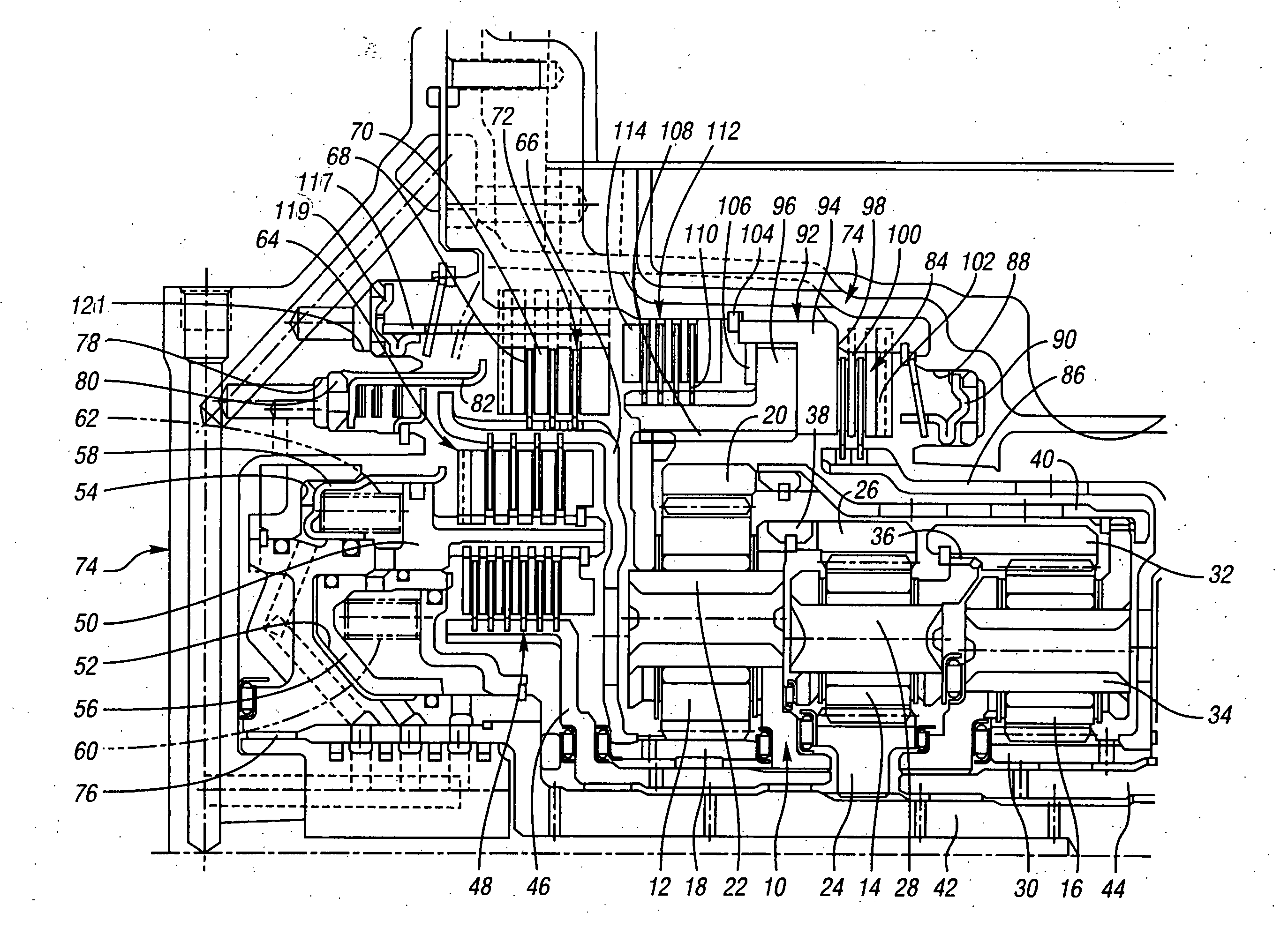
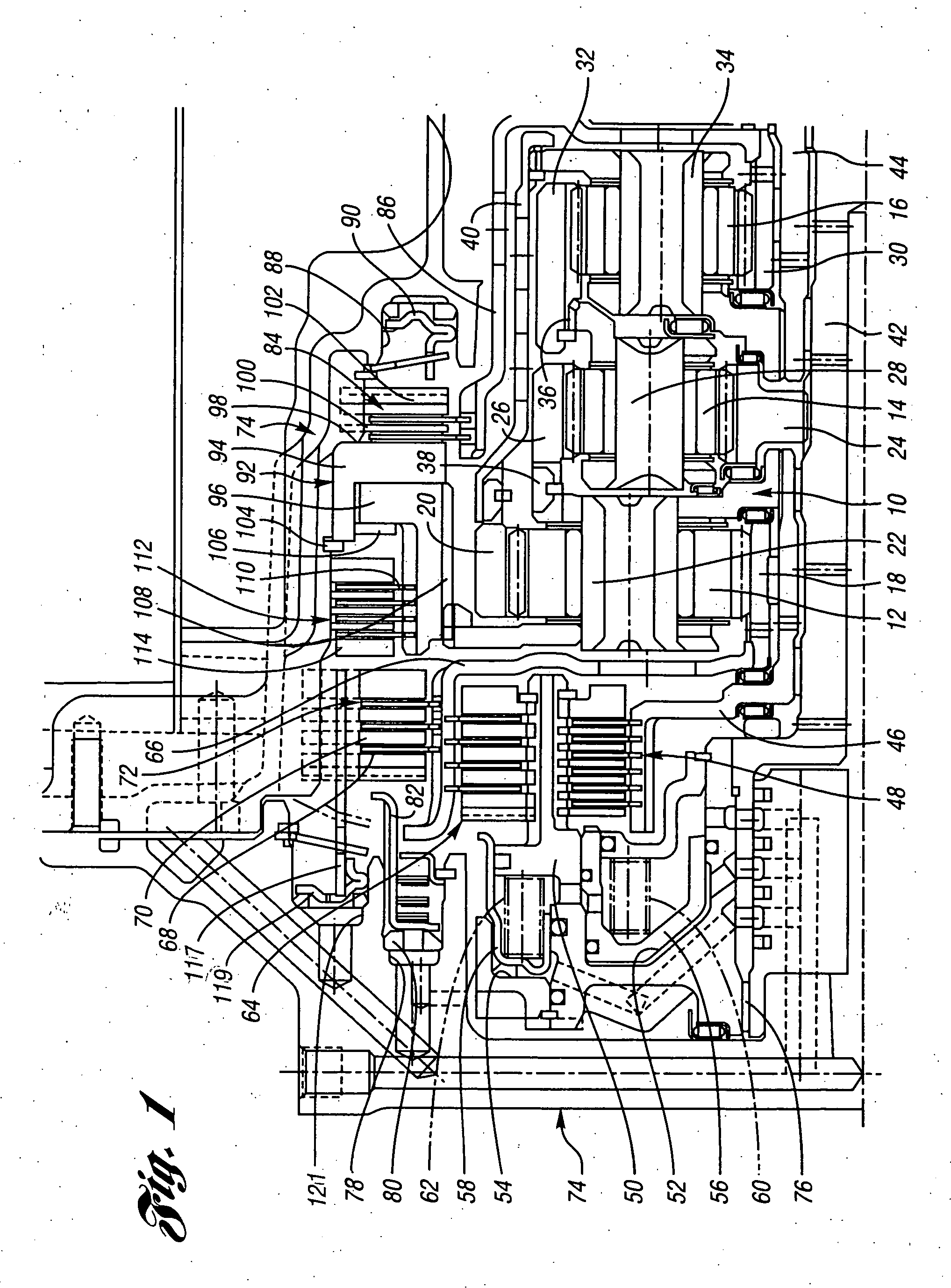
[0027] An automatic transmission gear system incorporating the invention is shown in the partial cross-sectional view of FIG. 1. It includes a planetary gearing arrangement 10, which comprises three simple planetary gear units 12, 14, and 16. Gear unit 12 includes a sun gear 18, a ring gear 20, and a planetary carrier 22. Gear unit 14 comprises a sun gear 24, a ring gear 26, and a planetary carrier 28. Gear unit 16 comprises a sun gear 30, a ring gear 32, and a planetary carrier 34.

[0028] Carrier 28 is drivably connected to sun gear 32, as shown at 36. Carrier 22 is drivably connected to ring gear 26, as shown at 38. Ring gear 20 is drivably connected to planetary carrier 34 by a torque transfer member 40.

[0029] A torque input shaft, which corresponds to the turbine shaft of a hydrokinetic torque converter (not shown), is designated by reference numeral 42. It is splined to sun gear 24. Torque output sleeve shaft 44 is splined to carrier 34, and carrier 22 is splined to friction c...


PUM


Abstract

A planar overrunning coupling assembly for a geared transmission. The coupling assembly has a circular pocket plate, a notch plate, and torque transmitting struts in pockets formed in the pocket plate. The geometry of the pockets prevents displacement of the struts toward the notch plate under the influence of centrifugal force when the pocket plate overruns the notch plate. The pocket plate and the notch plate define in part friction disc coupling assemblies.

Description

BACKGROUND OF THE INVENTION [0001] 1. Field of the Invention [0002] The invention relates to a planar coupling assembly for establishing and disestablishing a torque flow path in a geared multiple-ratio transmission for an automotive vehicle powertrain. [0003] 2. Background Art [0004] Prior art U.S. Pat. No. 5,964,331 discloses a one-way clutch comprising a pocket plate and a notch plate situated in a juxtaposed adjacent relationship. One-way clutches of this kind are sometimes referred to as planar clutches because the adjacent juxtaposed surfaces are situated in radial planes with respect to the axis of the clutch. [0005] For purposes of this disclosure, the term coupling should be interpreted to include clutches or brakes wherein one of the plates is drivably connected to a torque delivery element of a transmission and the other plate is drivably connected to another torque delivery element or is anchored and held stationary with respect to a transmission housing. The terms coupl...

Claims


Application Information

Patent Timeline
IPC IPC(8): F16D41/12F16D47/04F16H3/66
CPCF16D41/125F16D47/04F16H2200/201F16H2200/0052F16H3/66F16D41/12
Inventor RUTH, STEPHEN M.
Owner MEANS IND INC
Why Eureka
Try Eureka