A kind of rc-ligbt device and preparation method thereof
A device and dielectric layer technology, which is applied in the field of power semiconductor integrated circuits, can solve the problems that the PN junction cannot be opened normally, affects the stability and reliability of LIGBT devices, and the PN junction conduction voltage drop increases.
- Summary
- Abstract
- Description
- Claims
- Application Information
AI Technical Summary
Problems solved by technology
Method used
Image
Examples
Embodiment 1
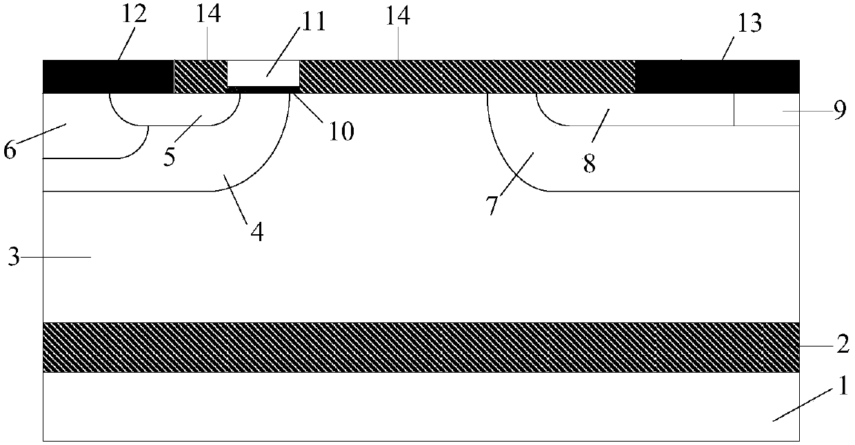
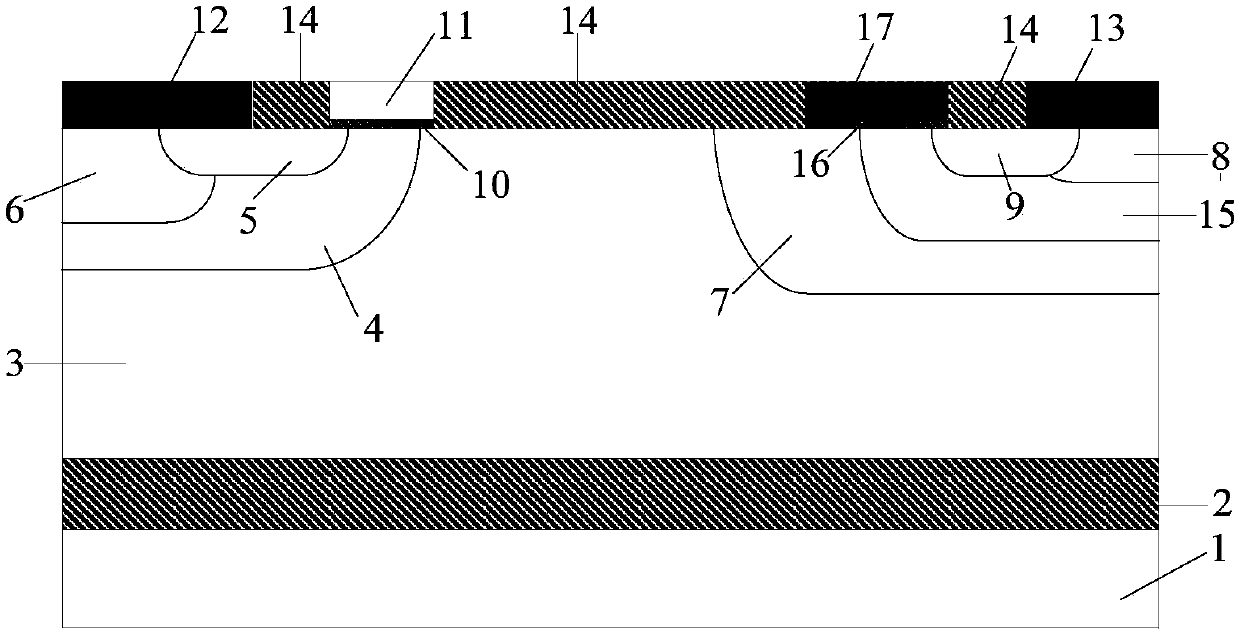
[0034] This embodiment provides an RC-LIGBT device with a voltage level of 400V, and its cell structure is as follows figure 2 As shown, it includes a substrate 1, a silicon oxide dielectric layer 2 on the substrate 1, an N-type drift region 3 on the silicon oxide dielectric layer 2, an emitter structure on the N-type drift region 3, a gate structure, The collector structure and the first dielectric layer 14; the emitter structure is composed of a P-type base region 4, an N+ source region 5, a P+ contact region 6 and a metal emitter 12, wherein the P-type base region 4 is set on the N-type drift In region 3 and located on the left side of its top, P+ contact region 6 and N+ source region 5 are independently arranged in P-type base region 4, and the front surfaces of P+ contact region 6 and N+ source region 5 are both in phase with metal emitter 12 Contact; the gate structure is located on the side of the emitter structure and consists of a gate dielectric 10 and a polysilicon...
Embodiment 2
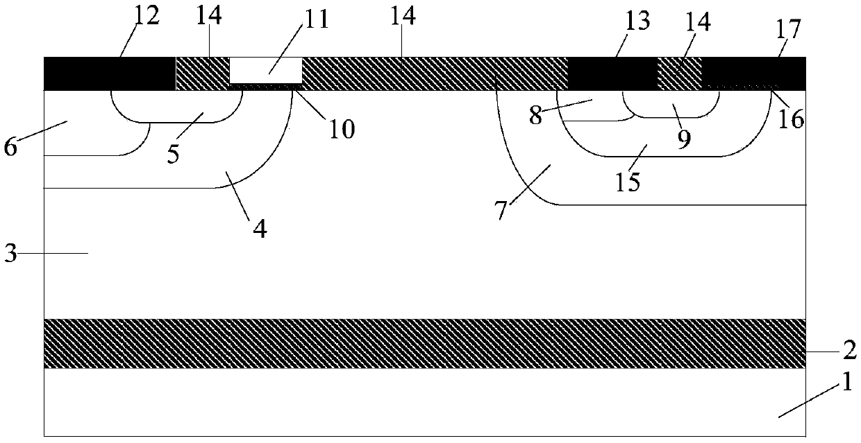
[0037] This embodiment provides an RC-LIGBT device with a voltage level of 400V, and its cell structure is as follows image 3 As shown, it includes a substrate 1, a silicon oxide dielectric layer 2 on the substrate 1, an N-type drift region 3 on the silicon oxide dielectric layer 2, an emitter structure on the N-type drift region 3, a gate structure, A collector structure and a dielectric layer 14; the emitter structure is composed of a P-type base region 4, an N+ source region 5, a P+ contact region 6 and a metal emitter 12, wherein the P-type base region 4 is arranged in the N-type drift region 3 and located on the left side of its top, the P+ contact region 6 and the N+ source region 5 are independently arranged in the P-type base region 4, and the front surfaces of the P+ contact region 6 and the N+ source region 5 are in contact with the metal emitter 12; The gate structure is located on the right side of the emitter structure and is composed of a gate dielectric 10 and ...
PUM
| Property | Measurement | Unit |
|---|---|---|
| Thickness | aaaaa | aaaaa |
| Thickness | aaaaa | aaaaa |
| Thickness | aaaaa | aaaaa |
Abstract
Description
Claims
Application Information
 - R&D
- Intellectual Property
- Life Sciences
- Materials
- Tech Scout
- Unparalleled Data Quality
- Higher Quality Content
- 60% Fewer Hallucinations
Browse by: Latest US Patents, China's latest patents, Technical Efficacy Thesaurus, Application Domain, Technology Topic, Popular Technical Reports.
© 2025 PatSnap. All rights reserved.Legal|Privacy policy|Modern Slavery Act Transparency Statement|Sitemap|About US| Contact US: help@patsnap.com


