A kind of rc-ligbt device and preparation method thereof

A device, N-type technology, used in semiconductor/solid-state device manufacturing, semiconductor devices, electrical components, etc., can solve the problem that the PN junction cannot be turned on normally, affect the stability and reliability of the LIGBT device, and increase the voltage drop of the PN junction. And other issues

Active Publication Date: 2019-05-10
UNIV OF ELECTRONICS SCI & TECH OF CHINA
View PDF3 Cites 0 Cited by
  • Summary
  • Abstract
  • Description
  • Claims
  • Application Information

AI Technical Summary

Problems solved by technology

Under low temperature conditions, the turn-on voltage drop of the PN junction formed by the P-type collector region 8 and the N-type electric field cut-off region 7 increases, and it needs to be turned on under a larger current condition, resulting in a more obvious negative resistance phenomenon. , and even cause the PN junction formed by the P-type collector region 8 and the N-type electric field stop region 7 in the device to fail to open normally, which seriously affects the stability and reliability of LIGBT devices

Method used


Image

  • A kind of rc-ligbt device and preparation method thereof
  • A kind of rc-ligbt device and preparation method thereof
  • A kind of rc-ligbt device and preparation method thereof

Examples


Embodiment 1

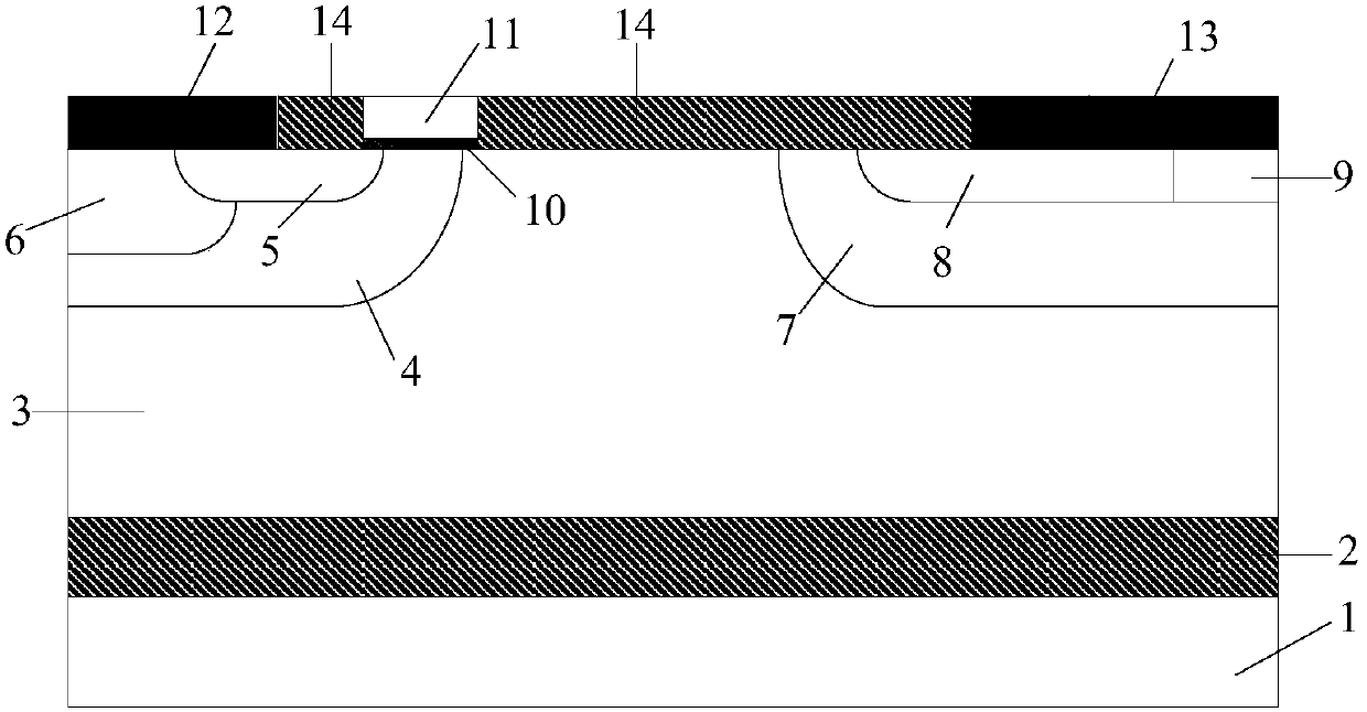
[0035] This embodiment provides an RC-LIGBT device with a voltage level of 400V, and its cell structure is as follows figure 2 As shown, it includes a substrate 1, a silicon oxide dielectric layer 2 located on the substrate 1, an N-type drift region 3 located on the silicon oxide dielectric layer 2, an emitter structure located on the N-type drift region 3, a gate structure, Collector structure and dielectric layer 14; the emitter structure is composed of P-type base region 4, N+ source region 5, P+ contact region 6 and metal emitter 12, wherein P-type base region 4 is arranged in N-type drift region 3 In the middle and on the left side of its top, the P+ contact region 6 and the N+ source region 5 are independently arranged in the P-type base region 4, and the front surfaces of the P+ contact region 6 and the N+ source region 5 are both in contact with the metal emitter 12; The gate structure is located on the right side of the emitter structure, and is composed of a gate di...

Embodiment 2

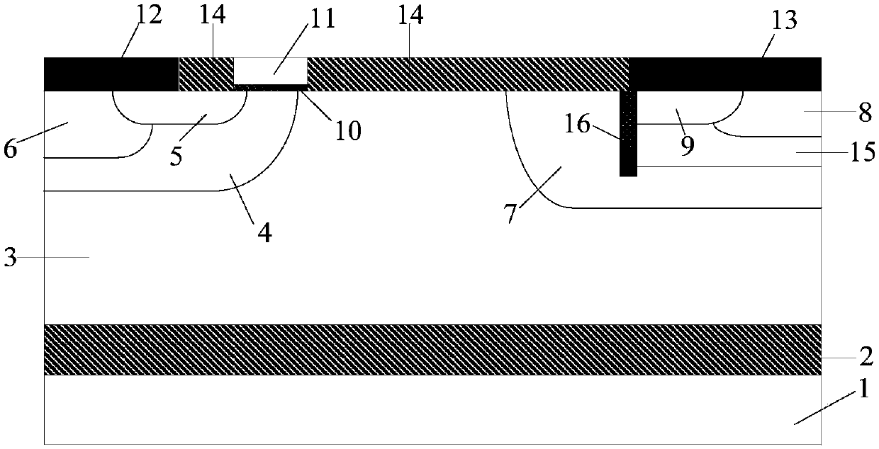
[0038] This embodiment provides an RC-LIGBT device with a voltage level of 400V, and its cell structure is as follows image 3 As shown, it includes a substrate 1, a silicon oxide dielectric layer 2 located on the substrate 1, an N-type drift region 3 located on the silicon oxide dielectric layer 2, an emitter structure located on the N-type drift region 3, a gate structure, Collector structure and dielectric layer 14; the emitter structure is composed of P-type base region 4, N+ source region 5, P+ contact region 6 and metal emitter 12, wherein P-type base region 4 is arranged in N-type drift region 3 In the middle and on the left side of its top, the P+ contact region 6 and the N+ source region 5 are independently arranged in the P-type base region 4, and the front surfaces of the P+ contact region 6 and the N+ source region 5 are both in contact with the metal emitter 12; The gate structure is located on the right side of the emitter structure, and is composed of a gate die...


PUM


Abstract

The invention belongs to the field of power semiconductor integrated circuits, in particular to a lateral reverse conduction insulated gate bipolar transistor (Reverse Conducting-LIGBT, RC-LIGBT) and a preparation method thereof, which are used to suppress the negative resistance (snapback) of a traditional RC-LIGBT device phenomenon, while improving the characteristics of the reverse diode, improving the stability and reliability of the device. The RC-LIGBT device of the present invention completely shields the influence of the N-type collector region on the conduction characteristics through the composite structure introduced at the collector terminal of the device in the forward LIGBT working mode, completely eliminates the negative resistance (snapback) phenomenon, and It has the same low turn-on voltage drop as the traditional LIGBT, which improves the stability and reliability of the device; at the same time, it provides a low-resistance freewheeling channel at the collector terminal in the reverse diode freewheeling mode, optimizing its freewheeling capability with a small turn-on voltage drop.

Description

technical field [0001] The invention belongs to the field of power semiconductor integrated circuits, relates to a lateral insulated gate bipolar transistor (Lateral Insulated Gate Bipolar Transistor, LIGBT), in particular to a lateral reverse conducting insulated gate bipolar transistor (Reverse Conducting-LIGBT, RC-LIGBT) and its preparation method. Background technique [0002] Lateral Insulated Gate Bipolar Transistor (LIGBT) is a new type of device in power integrated circuits. It not only has the advantages of easy driving, simple control and easy integration of LDMOSFET, but also reduces the on-voltage of the power transistor, large on-state current and low loss. It has become one of the core devices of modern power semiconductor integrated circuits. Literature (Shigeki T., Akio N., Youichi A., Satoshi S. and Norihito T. Carrier-Storage Effect and Extraction-Enhanced Lateral I GBT (E 2 LIGBT): A Super-High Speed ​​and Low On-state VoltageLIGBT Superior to LDM OSFET....

Claims


Application Information

Patent Timeline
Patent Type & Authority Patents(China)
IPC IPC(8): H01L21/331H01L29/739H01L29/417
CPCH01L29/41708H01L29/66325H01L29/7393
Inventor 张金平熊景枝田丰境刘竞秀李泽宏任敏张波
Owner UNIV OF ELECTRONICS SCI & TECH OF CHINA
Why Eureka
Try Eureka