Rotating torque-transmitting apparatus

a technology of rotating torque and transmission apparatus, which is applied in the direction of rotary clutches, fluid couplings, couplings, etc., can solve the problems of generating noise within the system, imposing significant bearing load on the bearing between the piston and the transmission plate, and affecting the performance of the transmission plate, so as to reduce the load

Inactive Publication Date: 2005-12-22
GM GLOBAL TECH OPERATIONS LLC
View PDF13 Cites 66 Cited by
  • Summary
  • Abstract
  • Description
  • Claims
  • Application Information

AI Technical Summary

Benefits of technology

[0011] In a yet further aspect of the present invention, the motion-limiting member cooperates with the rotating housing to enclose the return spring as...

Problems solved by technology

The seal members provide a leakage path for a portion of the oil, which is not desirable.
When the return spring is disposed between the stationary piston and the stationary portion of the housing, the apply plate is free and can generate noise within the system.
Generally, when the return spring is placed between the rotating housing and the apply plate, a significant beari...

Method used


Image

  • Rotating torque-transmitting apparatus
  • Rotating torque-transmitting apparatus
  • Rotating torque-transmitting apparatus

Examples


Embodiment Construction

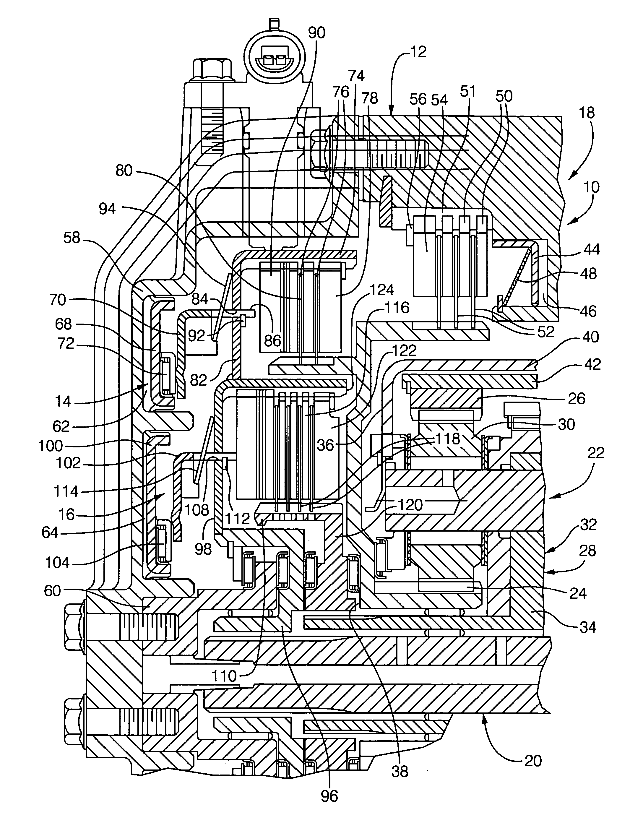
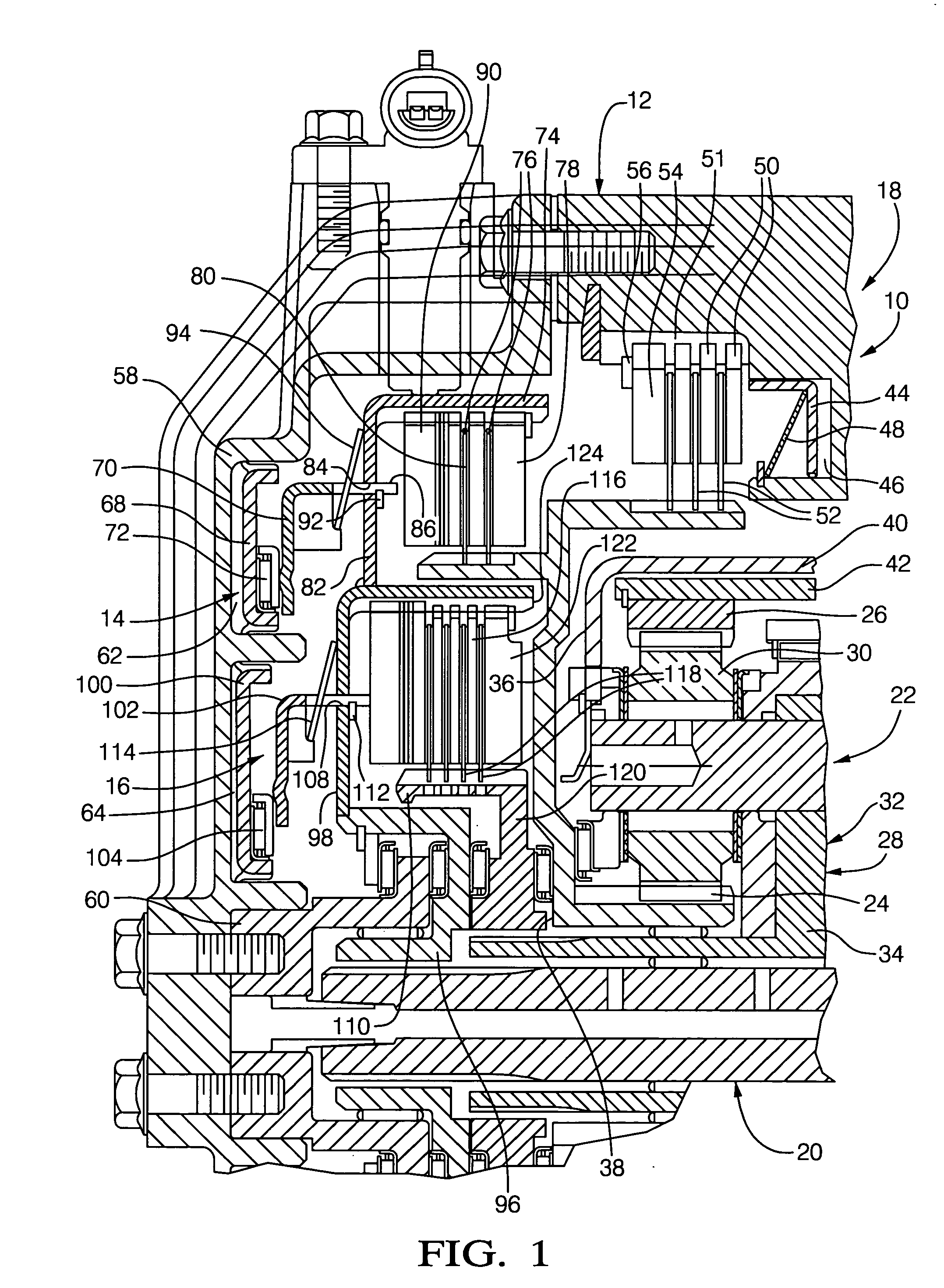
[0016]FIG. 1 depicts a portion 10 of a transmission including a transmission housing 12, a first torque-transmitting mechanism 14, a second torque-transmitting mechanism 16, a third torque-transmitting mechanism 18, an input shaft 20, and a planetary gearset 22.

[0017] The planetary gearset 22 includes a sun gear member 24, a ring gear member 26, and a planet carrier assembly member 28. The planet carrier assembly member 28 includes a plurality of pinion gears 30 rotatably mounted on a planet carrier member 32 and disposed in meshing relationship with both the sun gear member 24 and the ring gear member 26. The planet carrier member 32 includes a pair of side plates 34 and 36. The sun gear member 24 is connected with a hub portion 38. The planet carrier member side plate 36 is secured to a hub or drum member 40 and the ring gear member 26 is secured to a hub member 42.

[0018] The torque-transmitting mechanism 18 includes an apply piston 44, which is slidably disposed in an apply cha...


PUM


Abstract

A rotatable torque-transmitting apparatus includes a stationary piston and a rotatable apply plate. The rotatable apply plate is disposed adjacent a rotatable housing and separated therefrom by a return spring assembly which in a preload condition is trapped between the apply plate and the rotatable housing to limit the disengaged force which is transmitted between the rotatable housing and the stationary piston.

Description

TECHNICAL FIELD [0001] This invention relates to rotating torque-transmitting apparatus and, more particularly, to rotating torque-transmitting apparatus having a stationary apply piston. BACKGROUND OF THE INVENTION [0002] Automatic power transmissions having planetary gearsets employ a plurality of torque-transmitting mechanisms. The torque-transmitting mechanisms take the form of stationary type and rotating type. Stationary type torque-transmitting mechanisms are commonly termed brakes, and rotating type torque-transmitting mechanisms are commonly termed clutches. [0003] The stationary type torque-transmitting mechanism has at least one portion of that mechanism; namely, a plurality of disc members, drivingly connected through a spline with a stationary housing. Therefore, a stationary piston can be placed in that housing such that rotating drag forces cannot affect the piston. It is also simpler to direct hydraulic fluid through a stationary housing to a stationary piston. [0004...

Claims


Application Information

Patent Timeline
IPC IPC(8): F16D13/58F16D25/0638F16D25/10F16D25/12F16D33/00
CPCF16D13/585F16D25/0638F16D2048/0212F16D25/12F16D25/10F16D25/083F16D2013/581F16D67/04
Inventor SOWUL, HENRYKSTEVENSON, PAUL D.
Owner GM GLOBAL TECH OPERATIONS LLC
Why Eureka
Try Eureka