
Flash ADC receiver with reduced errors

a technology of flash adc and receiver, which is applied in the field of reducing decoding errors, can solve the problems of world channel imparting distortion to the signal, channel distortion, temporal spreading of the signal, etc., and achieve the effect of reducing the decoding errors of symbols at the receiver utilising flash analog to digital converters (adc)

Active Publication Date: 2005-12-22
CIENA
View PDF16 Cites 25 Cited by
  • Summary
  • Abstract
  • Description
  • Claims
  • Application Information

AI Technical Summary

Benefits of technology

[0005] Symbol decoding errors at a receiver utilising a flash analog to digital converter (ADC) can be reduced by adjusting a reference voltage level of the ADC where a decoding error rate at the reference voltage level exceeds a threshold.
[0008] In accordance to a further aspect of the present invention, there is provided in a receiver utilising a flash analog to digital converter (ADC), a method of improving link quality comprising: where a link quality at a voltage slicing level of said ADC does not meet a threshold, adjusting a reference voltage for said voltage slicing level.

Problems solved by technology

A real-world channel will impart distortions to the signal.
One significant cause of channel distortions results from temporal spreading of the signal when propagating over long distances or over nonlinear medium.
This phenonenon is not effectively addressed by known equalisers.

Method used


Image

  • Flash ADC receiver with reduced errors
  • Flash ADC receiver with reduced errors
  • Flash ADC receiver with reduced errors

Examples


Embodiment Construction

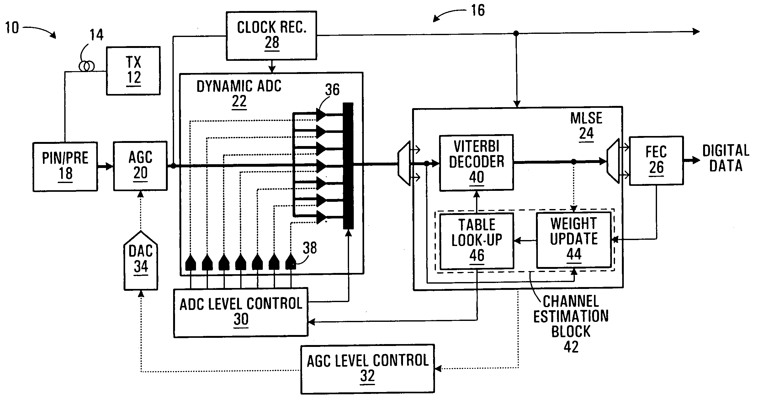
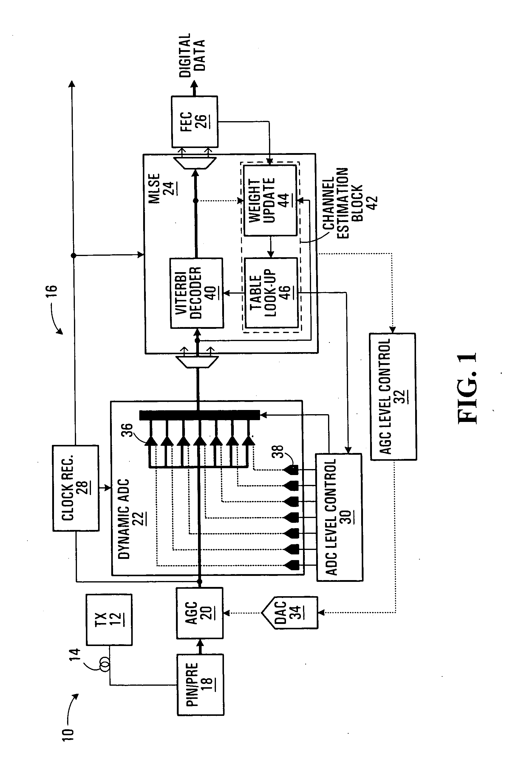
[0017] Turning to FIG. 1, a transmission system 10 comprises a transmitter 12, a channel 14, and a receiver 16. The channel may be, for example, an optical channel on an optical fibre. The receiver may comprise a serially arranged pre-processing block 18, adaptive gain controller (AGC) 20, flash ADC 22, equaliser 24, and forward error corrector (FEC) 26. A clock recovery block 28 may recover a clock signal upstream from the ADC and input the recovered clock to the ADC and the equaliser. The equaliser may output to an ADC level controller 30 which inputs reference voltages to the ADC 22. The equaliser 24 may also output to an AGC level controller 32, which in turn outputs to the AGC 20 through a digital to analog converter (DAC) 34. Each of the preprocessor 18, AGC level controller 32, and AGC 20 operate in a conventional manner and so is not further described herein.

[0018] As illustrated, the flash ADC 22 has (22−=1=) seven comparators 36, each input by any signal at the AGC 20. Th...


PUM


Abstract

Symbol decoding errors at a receiver utilising a flash analog to digital converter (ADC) can be reduced by adjusting a reference voltage level of the ADC where a decoding error rate at the reference voltage level exceeds a threshold.

Description

BACKGROUND [0001] This invention relates to the reduction of decoding errors when using a flash analog to digital converter. [0002] Telecommunications typically involves communicating a bit stream over a channel. At the sending end, the bit stream is typically encoded as an analog signal for transmission over the channel. At a receiver, the bit stream is decoded from the received analog signal. A real-world channel will impart distortions to the signal. It is the function of the receiver to endeavour to accurately recover the bit stream despite these distortions. [0003] Where a bit stream is encoded as an analog modulated (AM) signal, at the receiver, after removal of any carrier wave, the signal may pass through an analog to digital decoder (ADC). One known type of ADC is a flash ADC which uses a set of 2n−1 comparators to directly measure the received analog signal to a resolution of n bits. For example, a three bit flash ADC will have seven comparators, each of which compares an ...

Claims


Application Information

Patent Timeline
Patent Type & Authority Applications(United States)
IPC IPC(8): H03M1/06H03M1/08H03M1/12H03M1/18H03M1/36
CPCH03M1/0809H03M1/361H03M1/183H03M1/182
Inventor ROWLAND, ANDYLUK, TOMHADJIHASSAN, SEVGUI
Owner CIENA
Learn More