Method of generating a monitoring datagram

a datagram and data technology, applied in the field of packetswitched communications, can solve the problems of inability to determine the loss rate in mid-flow, complex packet loss measurement, and care to ensure that the reordered packets are not confused with lost packets, so as to achieve the effect of improving accuracy

Inactive Publication Date: 2005-12-22
AGILENT TECH INC
View PDF10 Cites 90 Cited by
  • Summary
  • Abstract
  • Description
  • Claims
  • Application Information

AI Technical Summary

Benefits of technology

[0041] It is thus possible to provide a method of constructing monitoring datagrams, as well as an apparatus for processing the monitoring datagrams, where the monitoring datagrams are not treated differently to other, content bearing, datagrams in terms of routing and queuing. It is also possible to measure datagram loss and delay across a Label Switched Path, not just at end-points, with improved accuracy over know techniques for measuring datagram loss and delay. Additionally, confidentiality of operational data of transit networks is preserved, because the shim entry pair corresponding to the monitoring status of the monitoring datagram is “pushed” further down the label stack. Consequently, monitoring datagrams are not recognised as such by routers of the transit networks.

Problems solved by technology

But even so, care must be taken not to confuse reordered packets with lost packets, particularly when the measurement points are not collocated with the originator and destination of the flow.
For flows that are more aggregated than microflows, or where a protocol being used is unable to assist in measuring packet loss, packet loss measurement is often more complex.
Sometimes, routers can be configured to capture packet and byte counts at the flow level, but whilst such information can be used to estimate traffic rates, it is less useful for determining loss rates in mid-flow due to the difficulty of sampling counters at monitoring points as a packet passes.
It is also not possible to base a solution on a Simple Network Management Protocol (SNMP), because information obtained from Management Information Bases (MIBs) is often slightly stale in some router architectures.
Therefore, a solution based upon SNMP is unattractive.
Consequently, measurements based on this technique tend to give only course-grained loss rates that reveal little as to how the rate varies over shorter time intervals.
The sophistication required in such techniques arises from a need to control the rate at which packets can pass the test when the monitoring points have no control over the makeup of the packets in the flow.
If the matched packets are too close together then the readings can become ambiguous, particularly when packets are frequently lost.
However, without reconfiguring the routers, it may be difficult to guarantee that injected test packets will be treated identically to all the other packets in a flow of packets; for example, the test packets may follow a different route to the destination of the flow of packets, or be subjected to different queuing treatment.
Also, the likelihood of packet reordering is increased, complicating the loss analysis.
However, this solution requires high volumes of active traffic to be injected to achieve statistically reliable results, and the potentially different QoS treatment of such packets makes it hard to draw any firm conclusions from such results.
However, this hybrid technique is, in fact, more problematic than other solutions when a monitoring point is downstream of a point where packets are generated.
Also, a passive probe clearly cannot modify packets as they pass the probe, and adding extension headers to user packets as the packets pass through a router may have some undesirable ramifications.

Method used


Image

  • Method of generating a monitoring datagram
  • Method of generating a monitoring datagram
  • Method of generating a monitoring datagram

Examples


Embodiment Construction

[0048] Throughout the following description identical reference numerals will be used to identify like parts.

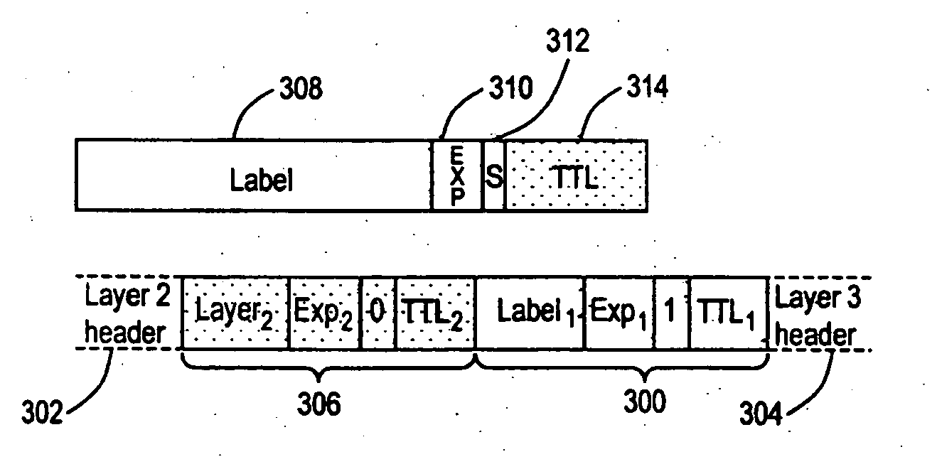
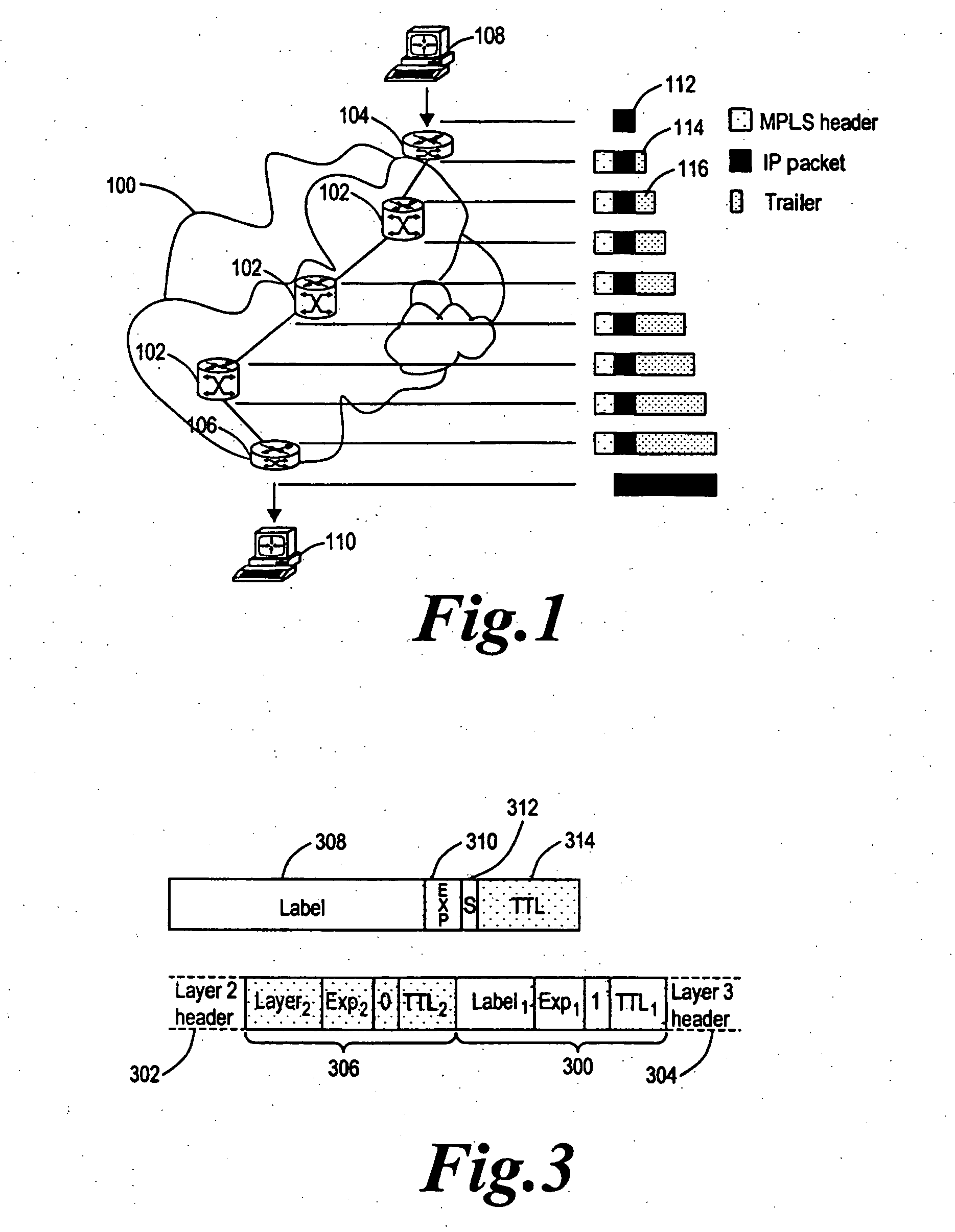
[0049] Referring to FIG. 1, a communications network, for example the Internet (not shown), can comprise a number of smaller networks, such as a Multi-Protocol Label Switching (MPLS) network 100 capable of supporting, for example a Virtual Private Network (VPN) with which a service level agreement is associated specifying acceptable datagram, or packet, loss rates.

[0050] The MPLS network 100 supports Label Switched Path (LSP) routing and the network 100 comprises a plurality of routers 102 to route packets between an ingress router 104 and an egress router 106. The ingress router 104 is capable of communicating with an ingress terminal 108, for example a first, suitably programmed, Personal Computer (PC), and the egress router 106 is capable of communicating with an egress terminal 110, for example a second, suitably programmed PC.

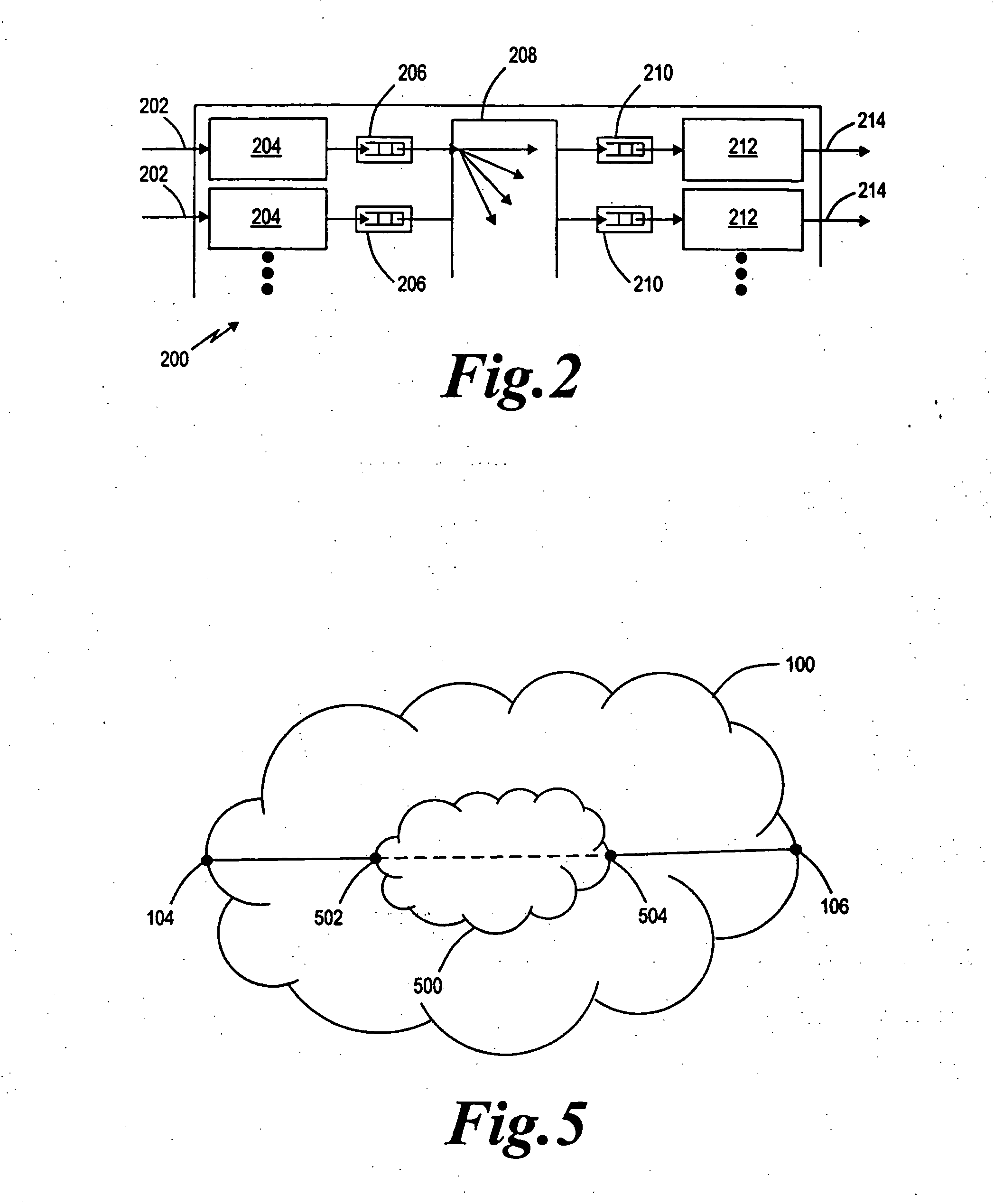
[0051] Referring to FIG. 2, each router 20...


PUM


Abstract

A method of generating a monitoring datagram for a predetermined network includes generating an initial datagram and encapsulating the initial datagram with a shim header, where the shim header has a first shim entry and a second shim entry, the first and second shim entries are associated with the predetermined network, the first shim entry is next to and follows the second shim entry, and where the first shim entry identifies the initial datagram as having a monitoring status.

Description

[0001] The present invention relates to a method of generating a monitoring datagram of the type used, for example, to harvest data from routers in a network, for example, a Multi-Protocol Label Switching network. The present invention also relates to a method of and apparatus for processing the monitoring datagram. BACKGROUND ART [0002] In the field of packet-switched communications, there is an increasing trend to communicate latency intolerant data over networks. The increasing use of real-time applications, such as high-quality video and audio, and Voice-over-IP traffic has resulted in a need to speed-up network traffic flow to meet the Quality of Service (QoS) standards required by such applications. [0003] Multi-protocol Label Switching (MPLS) is a standardised technology devised with the aim of increasing speed of traffic flow in networks, whilst making the networks easier to manage. MPLS networks are deployed within other networks. [0004] In MPLS, a packet, for example an In...

Claims


Application Information

Patent Timeline
Patent Type & Authority Applications(United States)
IPC IPC(8): H04L45/50
CPCH04L41/0213H04L45/502H04L45/00H04L43/026H04L43/00
Inventor MITCHELL, KEVIN
Owner AGILENT TECH INC
Why Eureka
Try Eureka