Clock adjustment apparatus and method thereof

a clock signal and clock technology, applied in the direction of pulse technique, transmission monitoring, generating/distributing signals, etc., can solve the problems of time lag between a clock signal and a data signal, system is not available for high speed transmission, etc., and achieve the effect of improving the time lag

Active Publication Date: 2005-12-22
FUJITSU LTD
View PDF21 Cites 2 Cited by
  • Summary
  • Abstract
  • Description
  • Claims
  • Application Information

AI Technical Summary

Benefits of technology

[0013] The present invention aims at offering a clock adjustment apparatus and a method thereof for improving the time lag between a clock signal and a data signal in a reception apparatus without transmitting a clock signal from a transmission apparatus to the reception apparatus.

Problems solved by technology

However, there is the following problem in the above-mentioned conventional transmission systems.
In the synchronous system (a), the clock signal and data signal are relatively lagged by both the piece-to-piece variations and a temperature / voltage fluctuation so that this system is not available for high speed transmission.
In the source synchronous system (b), the tolerance to the piece-to-piece variations and a temperature / voltage fluctuation are improved, but the time lag between a clock signal and a data signal becomes a problem when they are used in ultrahigh speed transmission.

Method used


Image

  • Clock adjustment apparatus and method thereof
  • Clock adjustment apparatus and method thereof
  • Clock adjustment apparatus and method thereof

Examples


Embodiment Construction

[0040] The following is the detailed explanation of the preferred embodiments of the present invention in reference to the drawings.

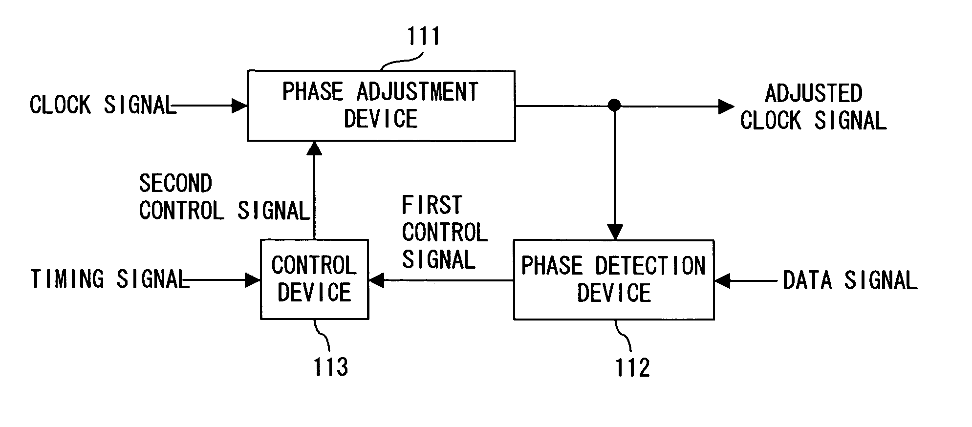
[0041]FIG. 2A shows the principle of a clock adjustment apparatus of the present invention. A clock adjustment apparatus of FIG. 2A comprises a phase adjustment device 111, a phase detection device 112 and a control device 113.

[0042] The phase adjustment device 111 delays an inputted clock signal and adjusts a phase of the delayed clock signal, thereby outputting the adjusted clock signal. The phase detection device 112 detects a phase relation between an inputted data signal and the adjusted clock signal and outputs a first control signal showing this phase relation. The control device 113 determines whether a delay amount of the phase adjustment device 111 is increased or decreased in accordance with the first control signal and generates a second control signal for increasing or decreasing the delay amount in accordance with an inputted timing sign...


PUM


Abstract

A clock adjustment apparatus delays a clock signal and adjusts a phase of the signal, thereby increasing or decreasing a delay amount of the clock signal in accordance with a phase relation between a data signal and an adjusted clock signal. The adjusted clock signal is used for receiving the data signal.

Description

BACKGROUND OF THE INVENTION [0001] 1. Field of the Invention [0002] The present invention relates to a signal transmission and reception circuit to be used for high speed digital transmission using a bus etc. inside a computer and specifically it relates to an apparatus and a method of adjusting the clock of a reception apparatus. [0003] 2. Description of the Related Art [0004] A conventional transmission method of synchronizing clock signals between a transmission apparatus and a reception apparatus includes mainly following two methods which are performed in a signal transmission and reception processing between the processor LSI (Large Scale Integration) circuit and the chip set LSI circuit of a computer. (a) Synchronous system [0005] As shown in FIG. 1A, clock signals are respectively distributed to a transmission apparatus 102 and a reception apparatus 103 as a strobe signal from a clock driver (CLK driver) 101 and data signals are transferred between these apparatuses. (b) S...

Claims


Application Information

Patent Timeline
Patent Type & Authority Applications(United States)
IPC IPC(8): G06F15/16H03L7/081H03L7/091H03L7/093H04L7/00H04L7/02H04L7/033
CPCH03L7/0814H03L7/093H03L7/091G06F15/16
Inventor YAMADA, JUN
Owner FUJITSU LTD
Why Eureka
Try Eureka