Ultrasonic speaker and projector

a technology applied in the field of ultrasonic speakers and projectors, can solve the problems of ineffective use of sound waves emitted to the backside, uneven sound pressure of reflected sounds, and insufficient use of sound waves from ultrasonic transducers, so as to achieve satisfactory directivity and enhance output sound pressures

Inactive Publication Date: 2005-12-22
SEIKO EPSON CORP
View PDF5 Cites 18 Cited by
  • Summary
  • Abstract
  • Description
  • Claims
  • Application Information

AI Technical Summary

Benefits of technology

[0014] An advantage of the invention is that it is possible to provide an ultrasonic speaker capable of utilizing all the sound waves emitted from both sound wave output surfaces of a push-pull electrostatic ultrasonic transducer as a sound source and a projector.
[0015] An ultrasonic speaker according to an aspect of the invention includes: a vibration film having a conductive layer; a pair of fixed electrodes provided oppositely to respective surfaces of the vibration film; and an ultrasonic transducer that causes the vibration film to generate sound waves by applying a DC bias voltage to the conductive layer of the vibration film while applying an alternating signal between the pair of fixed electrodes, and outputs the sound waves generated by the vibration film from two sound wave output surfaces via through-holes provided in each of the pair of fixed electrodes. The two sound wave output surfaces of the ultrasonic transducer are disposed in a direction intersecting with a sound wave emitting direction at right angles. Also, sound wave reflection plates are provided to both of the two sound wave output surfaces of the ultrasonic transducer, so that the sound waves outputted from each of the two sound wave output surfaces are reflected in the sound wave emitting direction.
[0016] When configured in this manner, in an ultrasonic speaker using a push-pull electrostatic ultrasonic transducer having two sound wave output surfaces, the ultrasonic transducer is disposed in such a manner that these sound wave output surfaces of the ultrasonic transducer are oriented in a direction that intersects with a sound wave emitting direction of the ultrasonic speaker. The sound wave reflection plates are then provided to both of the two sound wave output surfaces, so that the sound waves outputted from each of the two sound wave output surfaces are reflected in the sound wave emitting direction of the ultrasonic speaker.
[0017] The push-pull ultrasonic speaker is thus able to utilize (sound waves outputted from not only one of the two sound wave output surfaces but also the other one of the two sound wave output surface, which is not utilized, discarded in the related art). It is thus possible to enhance the output sound pressures, and consequently, a speaker having a satisfactory directivity can be fabricated.
[0018] In the ultrasonic speaker according to another aspect of the invention, the ultrasonic transducer is disposed in one of the following manners: (1) the two sound wave output surfaces are set to be parallel to a horizontal plane; and (2) the two sound wave output surfaces are set to be perpendicular to the horizontal plane.
[0019] When configured in this manner, in a case where the ultrasonic speaker is fabricated, it is possible to choose whether the sound output surfaces of the ultrasonic transducer are set to be parallel to the horizontal plane, or the sound output surfaces of the ultrasonic transducer are set to be perpendicular to the horizontal plane.

Problems solved by technology

According to the structure of this invention, however, sound wave output surfaces of the ultrasonic transducer array are not spaced at regular intervals with respect to the reflection surface, which poses a problem that sound pressures of reflected sounds are not uniform (for example, see JP-A-61-123389).
However, these two methods relate to a transducer having a single sound wave output surface, and sound waves emitted to the backside have not been used effectively in a push-pull electrostatic transducer of such a structure that sound waves are output in directions toward both surfaces of the transducer.
Therefore, the ultrasonic speaker is not configured to fully use all the sound waves outputted from the ultrasonic transducer.
Hence, when a reflection plate 60a is provided behind the circular fixed electrode 50, the reflection plate 60a needs to have a diameter twice as large as the diameter of the fixed electrode 50, which makes it difficult to easily fold the reflection plate 60a. This poses a problem in that the projector is increased in size or outputs of the ultrasonic speakers are insufficient (FIG. 12B shows a mode when the ultrasonic transducers shown in FIG. 12A are incorporated into the projector).

Method used


Image

  • Ultrasonic speaker and projector
  • Ultrasonic speaker and projector
  • Ultrasonic speaker and projector

Examples


Embodiment Construction

[0048] A best mode for carrying out the invention will now be described with reference to the accompanying drawings.

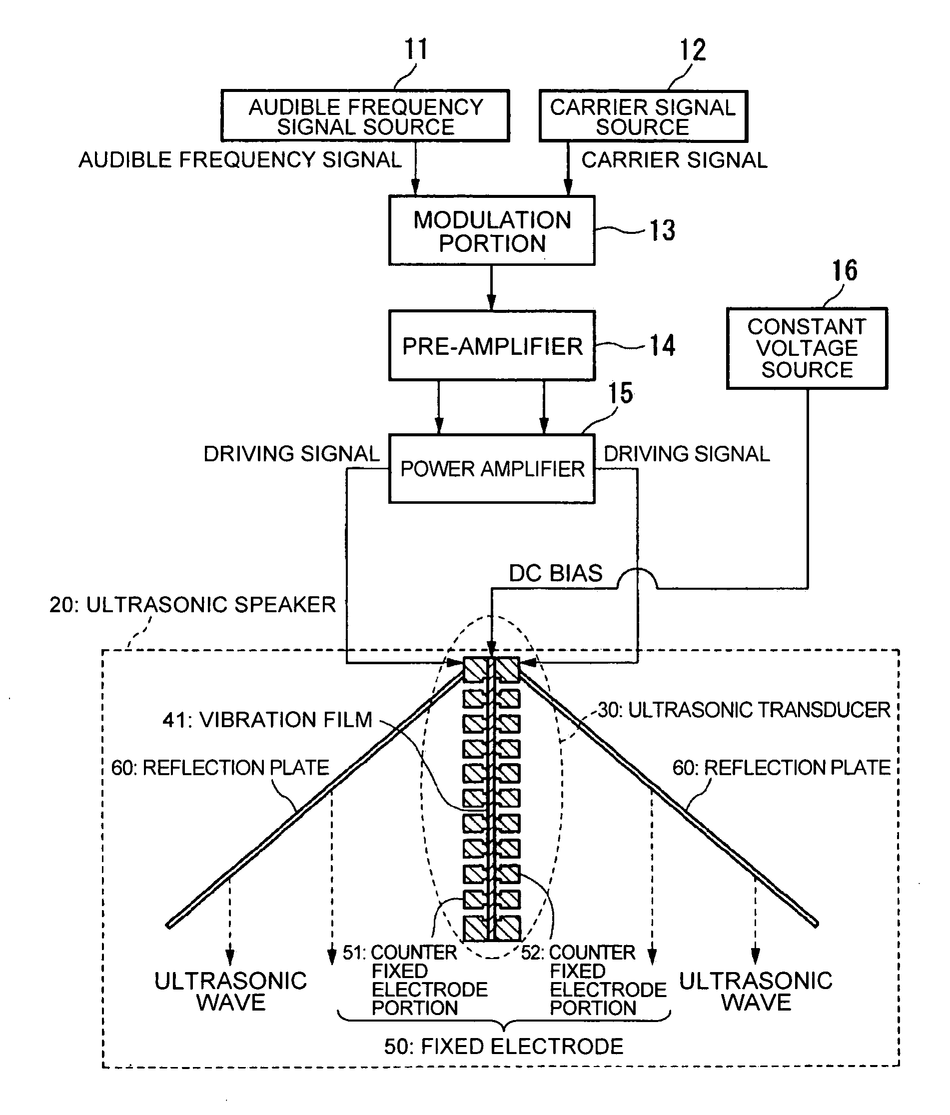
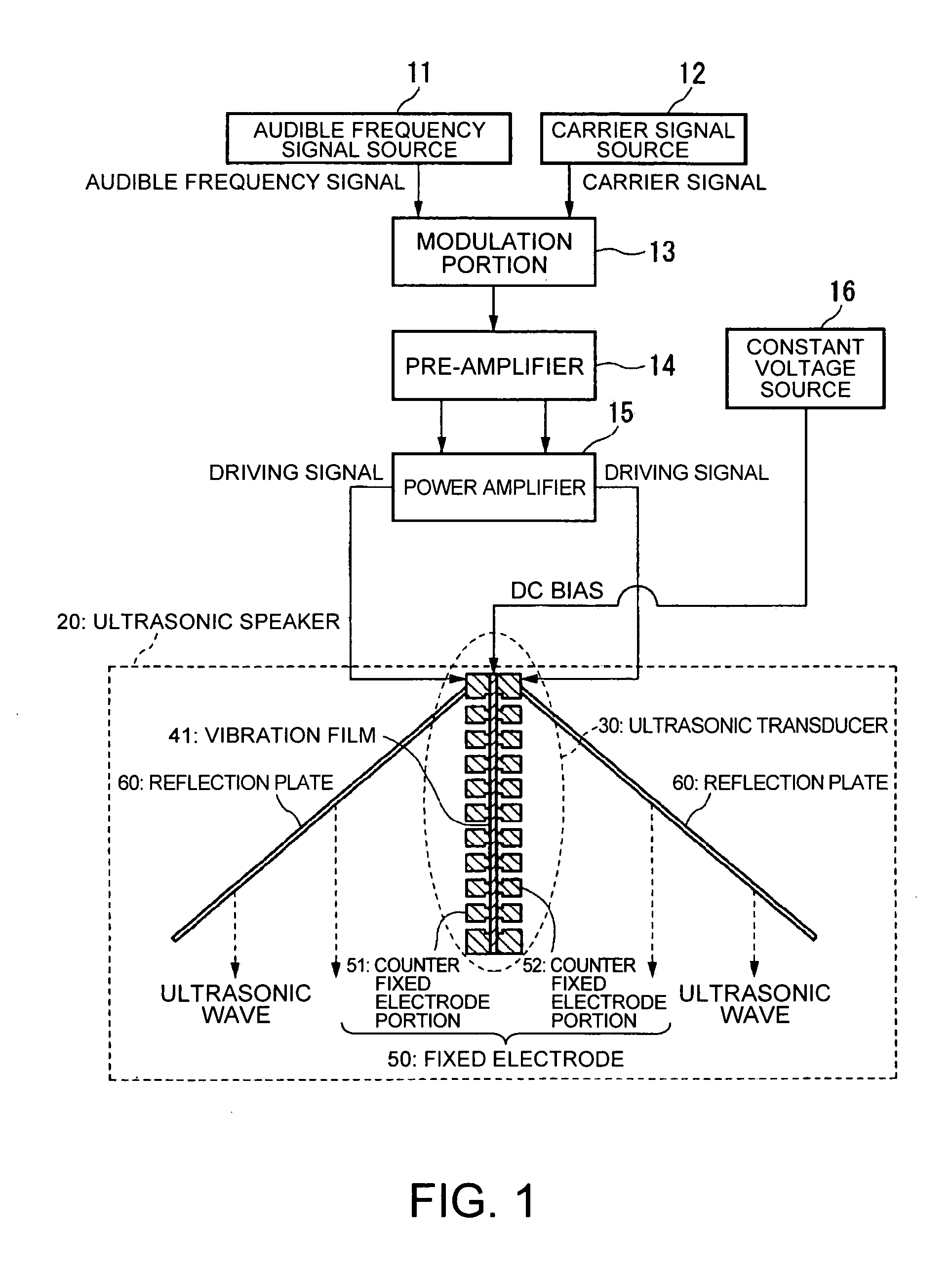
[0049]FIG. 1 is a view showing an example of the configuration of an ultrasonic speaker of the invention. Referring to FIG. 1, an audible frequency signal source 11 generates an audible frequency signal (for example, an audio signal). A carrier signal source 12 generates a carrier signal (carrier wave signal) in an ultrasonic frequency band. A modulation portion 13 modulates a carrier signal in the ultrasonic frequency band generated in the carrier signal source 12 into an audible frequency signal. A pre-amplifier 14 pre-amplifies a modulated signal, and a power amplifier 15 further amplifies the modulated signal. An ultrasonic transducer 30 converts the modulated signal amplified by the power amplifier 15 into a sound wave (ultrasonic wave) and emits the sound wave into air.

[0050] Ultrasonic waves emitted from the ultrasonic transducer 30 undergo the parametric effe...


PUM


Abstract

An ultrasonic speaker including: a vibration film having a conductive layer; a pair of fixed electrodes provided oppositely to respective surfaces of the vibration film; and an ultrasonic transducer that causes the vibration film to generate sound waves by applying a DC bias voltage to the conductive layer of the vibration film while applying an alternating signal between the pair of fixed electrodes, and outputs the sound waves generated by the vibration film from two sound wave output surfaces via through-holes provided in each of the pair of fixed electrodes. The two sound wave output surfaces of the ultrasonic transducer are disposed in a direction intersecting with a sound wave emitting direction at right angles. Also, sound wave reflection plates are provided to both of the two sound wave output surfaces of the ultrasonic transducer so that the sound waves outputted from each of the two sound wave output surfaces are reflected in the sound wave emitting direction.

Description

RELATED APPLICATIONS [0001] This application claims priority to Japanese Patent Application No. 2004-182464 filed Jun. 21, 2004 which is hereby expressly incorporated by reference herein in its entirety. BACKGROUND [0002] 1. Technical Field [0003] The present invention relates to an ultrasonic speaker and a projector incorporating the ultrasonic speaker, and more particularly, to an ultrasonic speaker capable of utilizing all the sound waves emitted from both sound wave output surfaces of a push-pull electrostatic ultrasonic transducer as a sound source and a projector. [0004] 2. Related Art [0005] Recently, applications related to a combination of speakers having a parametric effect that uses the non-linearity of air with respect to ultrasonic waves and a reflection plate that reflects audible sound waves have been filed. [0006] For example, a structure in which a reflection plate and an ultrasonic transducer array are incorporated into a speaker box is disclosed as an invention. A...

Claims


Application Information

Patent Timeline
Patent Type & Authority Applications(United States)
IPC IPC(8): A61B8/00B06B1/02G10K11/28H02N1/00H04R1/34H04R17/00H04R25/00
CPCB06B1/0292G10K11/28H04R2217/03H04R17/005H02N1/006
Inventor SEKINO, HIROKAZUMATSUZAWA, KINYAFUKUI, YOSHIKIMIYAZAKI, SHINICHI
Owner SEIKO EPSON CORP
Why Eureka
Try Eureka