Speaker Device

a technology of speaker and housing, which is applied in the direction of transducer details, metal diaphragms, electrical transducers, etc., can solve the problems of difficulty in achieving sufficient low-frequency sound reproduction, and achieve the effects of expanding the limit of low-frequency sound reproduction, reducing the acoustic stiffness inside the housing, and increasing the amplitude of the non-magnet member

Active Publication Date: 2007-11-29
PANASONIC CORP
View PDF11 Cites 9 Cited by
  • Summary
  • Abstract
  • Description
  • Claims
  • Application Information

AI Technical Summary

Benefits of technology

[0028] According to the first aspect, a force is applied to the non-magnet member included in the vibration member in a direction in which the displacement of the non-magnet member is increased, due to a magnetic field formed in the gap between the first and second magnetic circuits. Therefore, when the non-magnet member is vibrated by the driving force of the voice coil, the amplitude of the non-magnet member is increased by the magnetic field in the gap. Thereby, the acoustic stiffness inside the housing is relaxed, so that even a small-size housing vibrates as if the housing volume were large, thereby making it possible to expand the limit of reproduction of a low-frequency sound band. Also, the force applied to the non-magnet member is generated by the magnetic field formed in the gap between the first and second magnetic circuits. In other words, even when a thickness of the non-magnet member is reduced to some extent, a sufficient force can be generated by the magnetic field formed in the gap between the first and second magnetic circuits. Therefore, a lightweight can be achieved by making the non-magnet member thinner while maintaining the force which relaxes the acoustic stiffness. Thereby, a reduction in the output sound pressure level of the speaker device can be suppressed. Also, by disposing the first voice coil in the gap formed in at least one of the first and second magnetic circuits, the vibration system member is vibrated. In other words, the first and second magnetic circuits can play a role in applying a force in a direction which extends the displacement of the non-magnet member due to the magnetic field formed by the first and second magnetic circuits, and a role in applying a driving force to the first voice coil. According to the first aspect, a single magnet can serve both as a magnet for applying a force to the non-magnet member, and a magnet for applying a driving force to the voice coil, thereby making it possible to reduce the number of parts in the speaker device.
[0029] According to the second aspect, since at least a portion of the diaphragm is composed of the non-magnet member, a force for extending the displacement of the non-magnet member can be transferred to the diaphragm with high efficiency.
[0030] According to the third aspect, since the first and second magnetic circuits are not disposed on a sound emitting surface of the diaphragm, reproduced sound quality having a satisfactory directivity can be provided.
[0031] According to the fourth aspect, since the first and second magnetic circuits are not disposed on a sound emitting surface of the diaphragm, reproduced sound quality having a satisfactory directivity can be provided. Also, since the vibration system member is driven by the first and second voice coils, the output sound pressure level of the speaker device can be improved.
[0032] According to the fifth aspect, since the first and second magnetic circuits are not disposed on a sound emitting surface of the diaphragm, reproduced sound quality having a satisfactory directivity can be provided.
[0033] According to the sixth aspect, in the gap between the first and second magnetic circuits, a symmetric magnetic field distribution is formed in the vibration direction with respect to the non-magnet member disposed in the gap. Therefore, a distortion due to the asymmetry of a magnetic field distribution can be reduced.

Problems solved by technology

However, speaker devices for eventually reproducing sounds require large cabinets so as to sufficiently reproduce sounds in a low frequency region included in music sources.
Therefore, speaker devices carried in the small-size or portable players have small-volume cabinets, so that an acoustic stiffness exhibited by the cabinet is large, and therefore, it is difficult to achieve low-frequency sound reproduction to a sufficient extent.

Method used


Image

  • Speaker Device
  • Speaker Device
  • Speaker Device

Examples


first embodiment

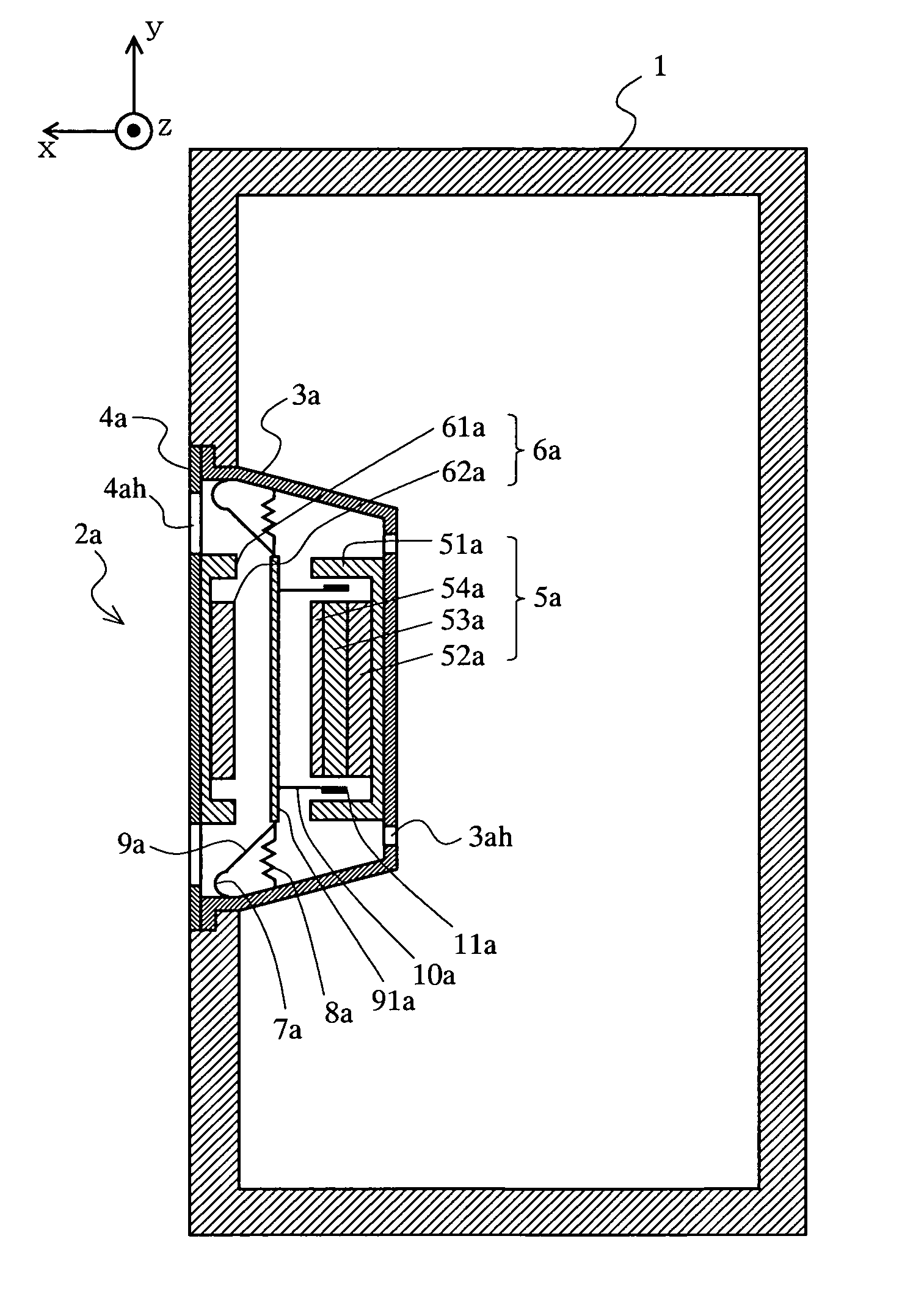
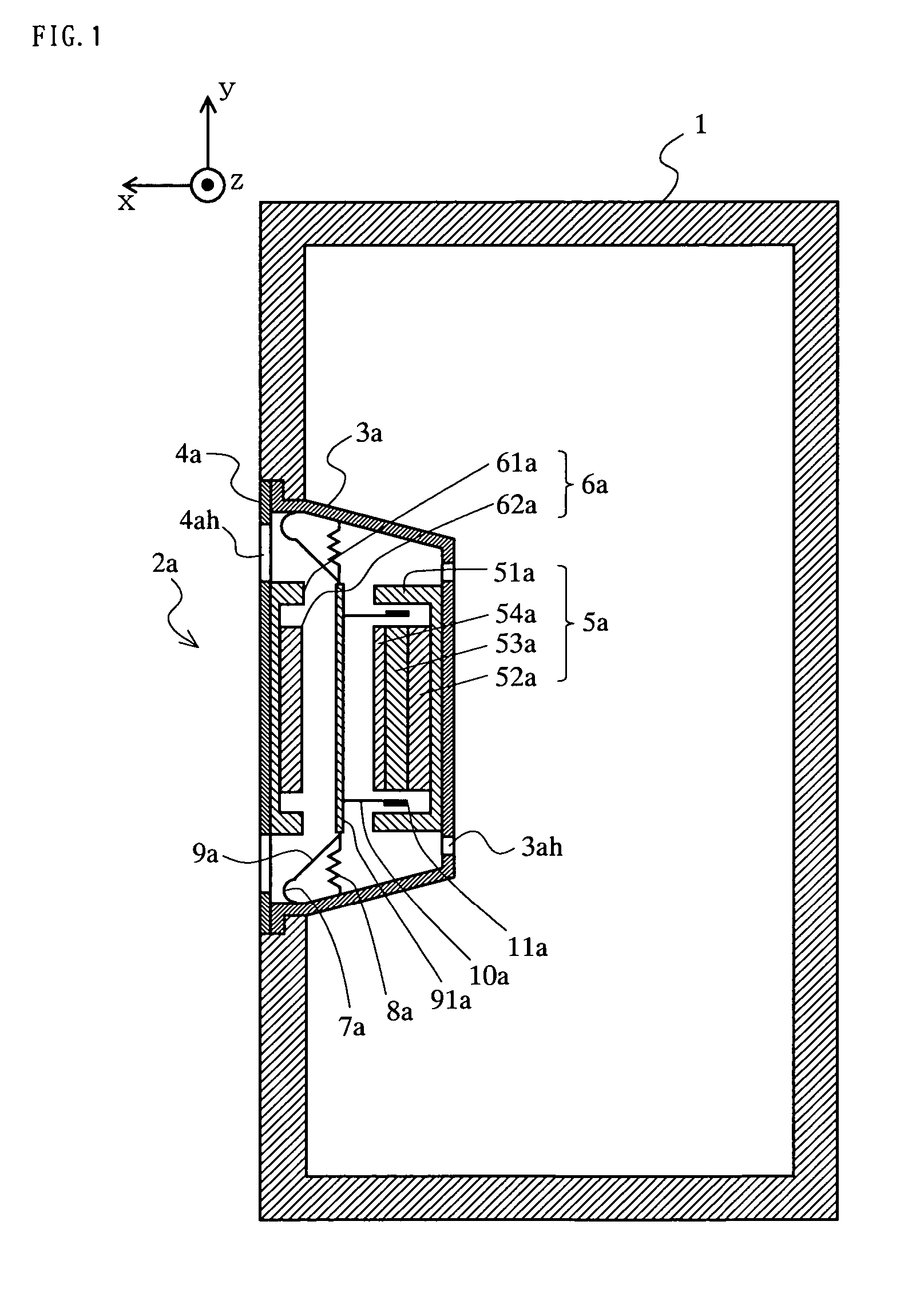
[0086] A speaker device according to a first embodiment of the present invention will be described with reference to FIG. 1. FIG. 1 is a cross-sectional view of a structure of the speaker device of the first embodiment. In FIG. 1, the speaker device of the first embodiment roughly comprises a cabinet 1 and a speaker unit 2a. The speaker unit 2a, which is in the shape of, for example, a circle, is attached to an opening portion formed in a front surface (the positive direction of an x axis) of the cabinet 1. The cabinet 1 is a housing which gives an acoustic stiffness to the speaker unit 2a. The speaker unit 2a is composed of a back surface frame 3a, a front surface frame 4a, a first magnetic circuit 5a, a second magnetic circuit 6a, an edge 7a, a damper 8a, a diaphragm 9a, a voice coil bobbin 10a, and a voice coil 11a.

[0087] The back surface frame 3a has a shape in which an inner portion thereof is projected in the shape of a convex with respect to an outer circumferential portion ...

second embodiment

[0102] A speaker device according to a second embodiment of the present invention will be described with reference to FIG. 3. FIG. 3 is a cross-sectional view of a structure of the speaker device of the second embodiment. In FIG. 3, the speaker device of the second embodiment roughly comprises a cabinet 1 and a speaker unit 2c. The speaker unit 2c, which is in the shape of, for example, a circle, is attached to an opening portion formed in a front surface (the positive direction of an x axis) of the cabinet 1. The cabinet 1 is a housing which gives an acoustic stiffness to the speaker unit 2c. The speaker unit 2c is different from the speaker unit 2a of the first embodiment in that both the first and second magnetic circuits both form magnetic gaps, and two voice coil bobbins and two voice coils are provided. Hereinafter, a structure of the speaker unit 2c will be described.

[0103] The speaker unit 2c is composed of a back surface frame 3c, a front surface frame 4c, a first magnetic...

third embodiment

[0120] A speaker device according to a third embodiment of the present invention will be described with reference to FIG. 5. FIG. 5 is a cross-sectional view of a structure of the speaker device of the third embodiment. In FIG. 5, the speaker device of the third embodiment roughly comprises a cabinet 1 and a speaker unit 2e. The speaker unit 2e, which is in the shape of, for example, a circle, is attached to an opening portion formed in a front surface (the positive direction of an x axis) of the cabinet 1. The cabinet 1 is a housing which gives an acoustic stiffness to the speaker unit 2e. The speaker unit 2e is different from the speaker unit 2c of the second embodiment in that a second magnetic circuit is supported by a column disposed in a gap between the second magnetic circuit and a first magnetic circuit, so that the front surface frame is no longer required, and an outer appearance thereof is similar to that of conventional speaker units, and that a magnetic material does no...


PUM


Abstract

A speaker device of the present invention roughly comprises a cabinet (1) and a speaker unit (2a). The speaker unit (2a) is attached to an opening portion formed in a front surface of the cabinet (1). The speaker unit (2a) has a back surface frame (3a), a front surface frame (4a), a first magnetic circuit (5a), a second magnetic circuit (6a), an edge (7a), a damper (8a), a diaphragm (9a), a voice coil bobbin (10a), and a voice coil (11a). A non-magnet member (91a) which is a portion of the diaphragm (9a), the first magnetic circuit (5a), and the second magnetic circuit (6a) play a role as a negative stiffness mechanism to suppress an influence of an acoustic stiffness, thereby achieving a small-size speaker device capable of reproducing low-frequency sound.

Description

TECHNICAL FIELD [0001] The present invention relates to a speaker device and, more particularly, to a speaker device which achieves low-frequency sound reproduction using a small-size cabinet. BACKGROUND ART [0002] Conventionally, audio devices are becoming more digitalized, and players for reproducing music sources are becoming smaller and more portable. However, speaker devices for eventually reproducing sounds require large cabinets so as to sufficiently reproduce sounds in a low frequency region included in music sources. Therefore, speaker devices carried in the small-size or portable players have small-volume cabinets, so that an acoustic stiffness exhibited by the cabinet is large, and therefore, it is difficult to achieve low-frequency sound reproduction to a sufficient extent. [0003] Therefore, a speaker device has been disclosed in which a limit of low-frequency sound reproduction which is determined by the volume of a cabinet is improved (see, for example, Patent Document...

Claims


Application Information

Patent Timeline
Patent Type & Authority Applications(United States)
IPC IPC(8): H04R1/28H04R9/02H04R9/04
CPCH04R1/22H04R9/025H04R9/04H04R2499/15H04R2400/11H04R2499/13H04R2307/027
Inventor MATSUMURA, TOSHIYUKISAIKI, SHUJI
Owner PANASONIC CORP
Why Eureka
Try Eureka