
Interference Checking Device

Inactive Publication Date: 2005-12-22
DMG MORI SEIKI CO LTD
View PDF4 Cites 42 Cited by
  • Summary
  • Abstract
  • Description
  • Claims
  • Application Information

AI Technical Summary

Benefits of technology

[0012] The present invention came about in consideration of the situation described above and has as its object to provide an interference checking device that is able to check for the presence of interference accurately and efficiently for all interference relationships that could arise in a machine tool.
[0031] Thus, with the interference checking device according to the present invention, the interference determination processor uses three-dimensional modeling data for the tool, the workpiece and the structures to automatically check for the presence of interference with regard to the interference relationships among the tool, the workpiece and the structures defined by interference data, so interference checking can be performed accurately and efficiently with regard to any kid of interference relationship.
[0032] Moreover, the determination of interference is performed according to movement commands in a block ahead of (succeeding) the block being executed by the control execution processor, so the presence of interference can be checked in advance before the drive mechanisms are driven and the structures are actually moved under the control of the control execution processor, and thus it is possible to reliably prevent interference from arising.
[0034] Moreover, if the interference checking device is provided with an image display device, and this image display device displays three-dimensional images of the structures that are moved according to the movement commands, and of the other structures, the workpiece and the tool, this is convenient because the operator will be able to visually check the movement of the structures through these images. In addition, the location where interference is occurring can be easily identified.

Problems solved by technology

This advance check of the machining program is done in this manner because, if such errors are present, there is a risk of serious accidents involving the tool, workpiece or other structures interfering with each other.
However, in the conventional example described above, the direction of travel, amount of travel and method of travel of the tool are displayed with vectors and there is a problem in that this display alone is not sufficient for the operator to accurately predict the positional relationships between the tool and workpiece after travel, and as a result, the operator cannot accurately determine whether interference is present or not.
Moreover, interference may occur in a machine tool not only between the tool and workpiece, but rather, for example, the tool rest may interfere with another structure during its travel, or when the spindle is indexed so that the workpiece rotating about its central axis comes to a predetermined angular position of rotation, the workpiece may interfere with the tool or another structure, so there is a possibility of other types of interference arising between the tool or workpiece and a structure or between structures, and these interfering relationships cannot be checked in the conventional example described above.

Method used


Image

  • Interference Checking Device
  • Interference Checking Device
  • Interference Checking Device

Examples


Embodiment Construction

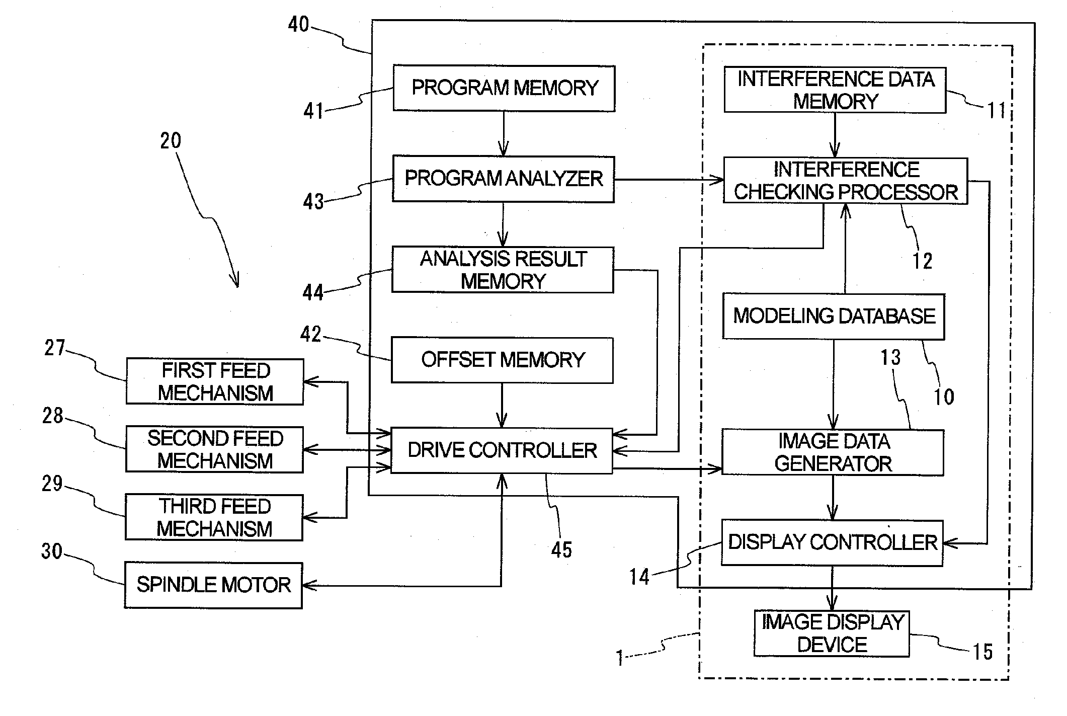
[0047] The following is a description of preferred embodiments of the present invention made with reference to the appended drawings. FIG. 1 is a schematic block diagram illustrating the constitution of an interference checking device according to a first embodiment of the present invention.

[0048] As shown in FIG. 1, the interference checking device 1 in this example is provided in a NC lathe 20 and comprises a modeling database 10, an interference data memory 11, an interference checking processor 12, an image data generator 13, a display controller 14 and an image display device 15.

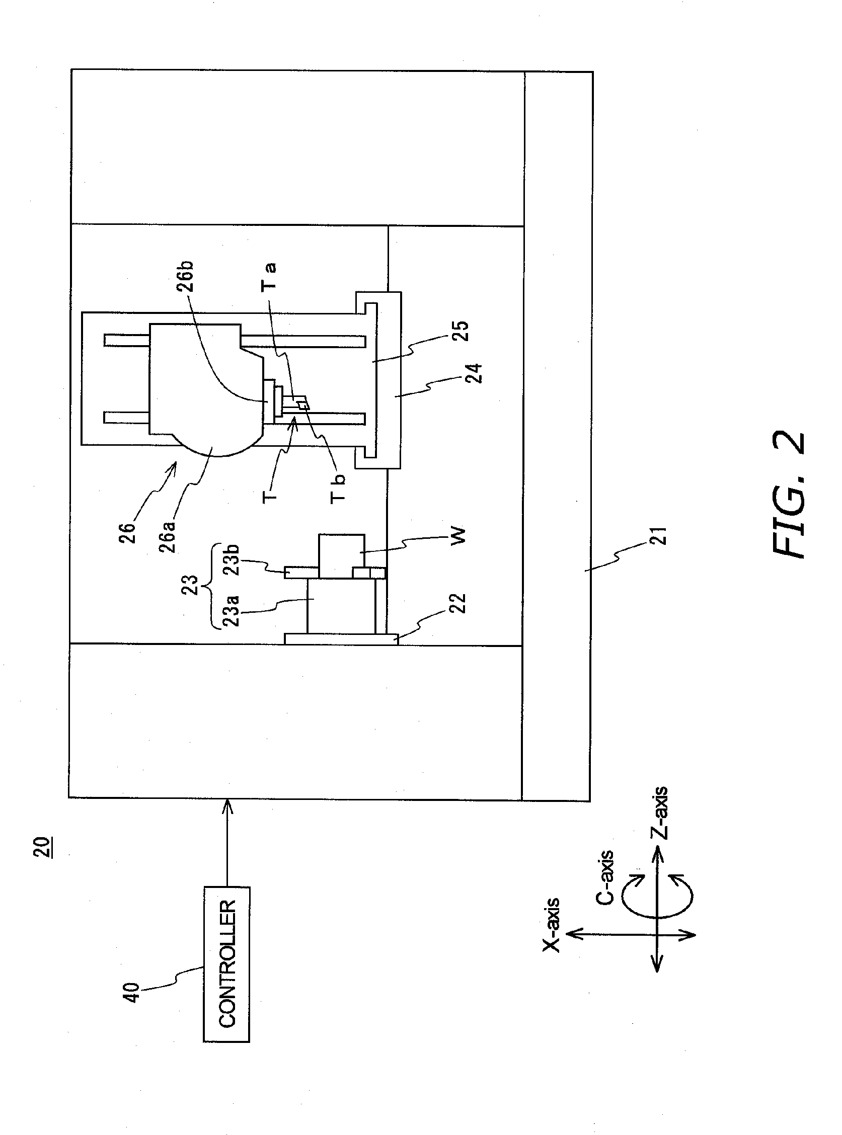
[0049] The NC lathe 20 will be explained first.

[0050] As shown in FIG. 1 and FIG. 2, the NC lathe 20 is constituted by comprising the structures of a bed 21, a headstock (not shown) disposed on the bed 21, a spindle 22 supported so as to be rotated around a horizontal central axis by the headstock (not shown) (around the Z-axis (in the direction of the C-axis)), a chuck 23 mounted to the spindle 22, ...


PUM


Abstract

Interference checking device including: a modeling database that stores data for three-dimensional modeling of tools, workpieces, and machine-tool constituting structures; an interference data memory for storing interference data defining inter-component interference relationships among the tool, the workpiece, and the structures; and an interference checking processor that, based on structure movement commands sent from a program analyzer for the machine tool, and on data stored in the modeling database and interference data memory, determines whether the tool, the workpiece, and the structures will interfere with each other. Movement commands in a block at least one block succeeding the block being executed in order to control the drive mechanisms that move the structures are sent from the program analyzer to the interference checking processor.

Description

BACKGROUND OF THE INVENTION [0001] 1. Technical Field [0002] The present invention-in machine tools furnished with a plurality of structures including at least tool- and workpiece-holding structures, and furnished with drive mechanisms for driving structures, among the plurality of structures, that are equipped to be movable, and with a controller for controlling the drive mechanisms based on a machining program—relates to interference-checking devices that check whether movement by the movable structures will cause the moving structures themselves, the other structures apart from the moving structures, or the tools or the workpieces to interfere with each other. [0003] 2. Description of the Related Art [0004] A lathe, which is one type of machine tool, comprises a plurality of structures, namely a bed, headstock, spindle, saddle, tool rest and tailstock, along with feed mechanisms that let the saddle, tool rest and tailstock travel, with the tool held in the tool rest and the workp...

Claims


Application Information

Patent Timeline
IPC IPC(8): G05B19/4061G05B19/4069G06F19/00
CPCG05B19/4069G05B2219/35314G05B2219/35333G05B2219/35318G05B2219/35324G05B2219/35316
Inventor NAKAMURA, TAKAYUKI
Owner DMG MORI SEIKI CO LTD
Learn More