Noise checking method and apparatus and computer-readable recording medium which records a noise checking program thereon

a noise checking and noise value technology, applied in the direction of noise figure or signal-to-noise ratio measurement, pulse characteristics measurement, instruments, etc., can solve the problems of large amount of work, large number of errors, and victims and aggressors not always working concurrently, so as to reduce the amount or correction of noise value errors, improve layout design freedom, and reduce the work needed for correction

Inactive Publication Date: 2005-12-22
FUJITSU LTD
View PDF8 Cites 6 Cited by
  • Summary
  • Abstract
  • Description
  • Claims
  • Application Information

AI Technical Summary

Benefits of technology

[0015] With the foregoing problems in view, one object of the present invention is to make it possible to extract victims that have problems in terms of timing, from the victims which are evaluated to have noise value er

Problems solved by technology

In actual LSIs, however, it is rare that all the logical cells connected to one wiring branch work concurrently, and some of the logical cells never work concurrently.
That is, victims and their aggressors do not always work concurrently.
In spite of this, all the victims whose noise values exceed the limit value are recognized as errors, so that the number of errors is greatly incre

Method used


Image

  • Noise checking method and apparatus and computer-readable recording medium which records a noise checking program thereon
  • Noise checking method and apparatus and computer-readable recording medium which records a noise checking program thereon
  • Noise checking method and apparatus and computer-readable recording medium which records a noise checking program thereon

Examples


first embodiment

[1] First Embodiment

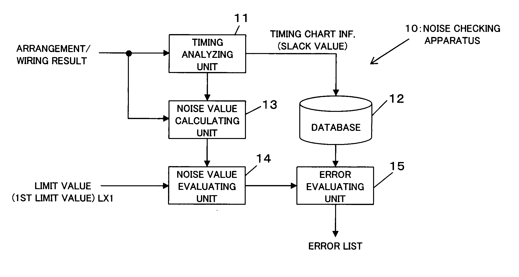
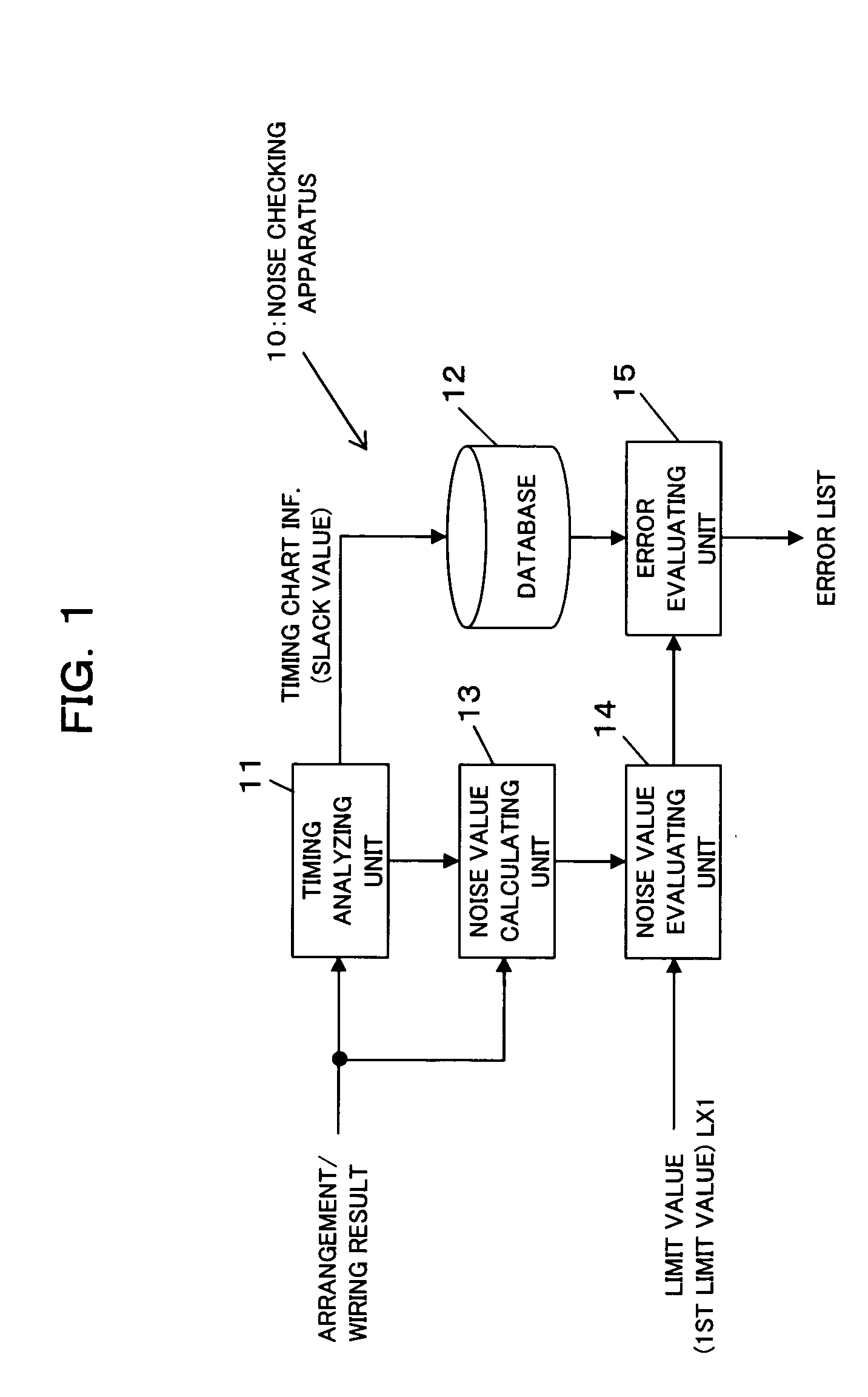
[0042]FIG. 1 is a block diagram showing a functional construction of a noise checking apparatus according to a first embodiment of the present invention. As shown in FIG. 1, a noise checking apparatus 10 of the first embodiment includes a timing analyzing unit 11, a database 12, a noise value calculating unit 13, a noise value evaluating unit 14, and an error evaluating unit 15. These elements are provided in an attempt to realize static noise checking on a result of cell arrangement and inter-cell wiring in integrated circuits such as LSIs, after the cell arrangement and the inter-cell wiring is carried out.

[0043] The timing analyzing unit 11 carries out delay simulation by use of timing analysis, based on the result of cell arrangement and the inter-cell wiring, to obtain a timing chart of signal transfer on each wire, and the timing analyzing unit 11 also calculates a slack value, which is a timing margin of the driver of each wire, and stores the thus obtain...

second embodiment

[2] Second Embodiment

[0072]FIG. 6 is a block diagram showing a functional construction of a noise checking apparatus according to a second embodiment of the present invention. A noise checking apparatus 20 of the second embodiment includes a timing analyzing unit 21, a database 22, a 1-to-1 noise value calculating unit 23, a 1-to-1 noise value evaluating unit 24, a 1-to-2 noise value calculating unit 25, a 1-to-2 noise value evaluating unit 26, a first error evaluating unit 27, a permissible upper limit value evaluating unit 28, and a second error evaluating unit 29. These elements are provided in an attempt to realize static noise checking on a result of cell arrangement and inter-cell wiring in integrated circuits, after the cell arrangement and the inter-cell wiring is carried out.

[0073] Here, the timing analyzing unit 21, database 22, 1-to-1 noise value calculating unit 23, and 1-to-1 noise value evaluating unit 24, are similar to the timing analyzing unit 11, database 12, nois...


PUM


Abstract

The apparatus reduces the amount of correction for noise value error, so as to reduce work needed for correction to ensure error avoidance, and to improve the freedom of layout design, and to reduce load on DA. Based on a timing chart of signal transfer on each wire, the last edge appearance timing in the signal waveform of a victim whose noise value exceeds a limit value is compared with the last edge appearance timing in the signal waveform of an aggressor, to evaluate the noise value error in the victim. The apparatus is used in static noise checking of cell arrangement and inter-cell wiring after such cell arrangement and inter-cell wiring are performed at design of integrated circuits such as LSIs.

Description

BACKGROUND OF THE INVENTION [0001] 1. Field of the Invention [0002] The present invention relates to a static noise checking technique, which is performed during the design of an integrated circuit such as an LSI (Large Scale Integration). The static noise check is performed after cell arrangement and inter-cell wiring, to carry out noise checking on the cell arrangement / inter-cell wiring. [0003] 2. Description of the Related Art [0004] Generally speaking, at design of integrated circuits such as LSIs, cell arrangement and inter-cell wiring are performed, and a noise value that may arise in each wire is calculated and checked. In cases where a noise value exceeding a limit value is caused, (that is, when a noise value error occurs), cell rearrangement and inter-cell rewiring are performed (for example, see Japanese Patent Application Publication Nos. HEI08-278992, HEI10-096762, 2001-217315, 2002-358341). [0005] Referring to FIG. 12A, FIG. 12B, and FIG. 13, a common LSI designing met...

Claims


Application Information

Patent Timeline
IPC IPC(8): G06F11/00G06F17/50H01L21/82
CPCG06F17/5036G06F30/367
Inventor ISHIKAWA, YOICHIRO
Owner FUJITSU LTD
Why Eureka
Try Eureka